Thermistor Module
Contents
[hide]Introduction
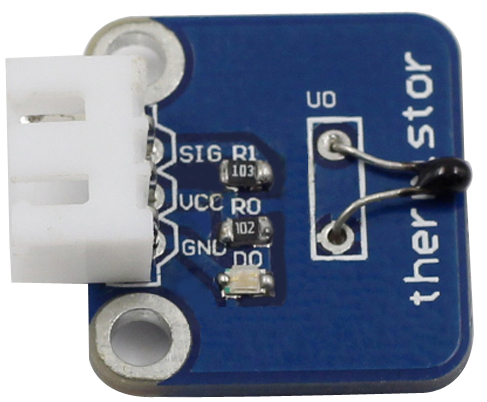
Thermistor is a sensitive element and divided into two types, PTC and NTC, which we mentioned above, by different temperature coefficients. Its resistance varies significantly with temperature. The resistance of PTC thermistor increases with higher temperature when that of NTC, decreases. The precision of NTC thermistors can be up to 0.1℃ and the time constant can be less than 10s. They are applied to thermo detectors in barn, as well as temperature measurement in food storing, medicine and health, ocean, etc.
the thermistor sensor module measures temperature sensitively though it can output only analog signals.

The schematic diagram of the module is as follows:

Thermistor in the experiment--Experimental Principle
The principle is that the resistance of the NTC thermistor changes with the temperature difference in the outer environment. It detects the real-time temperature of the environment. When the temperature gets higher, the resistance of the thermistor decreases and the voltage of pin A0 increases accordingly. The voltage data then is converted to digital quantities by the A/D adapter. The temperature in Celsius and Fahrenheit then is output via programming and then displayed on LCD1602.
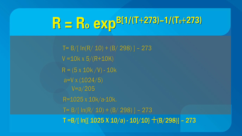
In this experiment a thermistor and a 10k pull-up resistor are used. Each thermistor has a normal resistance. Here it is 10k ohm, which is measured under 25 degree Celsius.
Here is the relation between the resistance and temperature change:

Thermistor in the experiment--Experimental Procedures
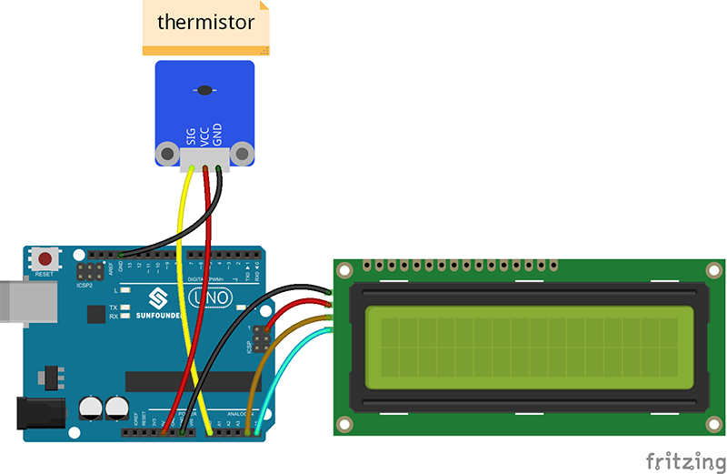
Step 1: Build the circuit

Step 2: Program (Please refer to the example code in LEARN -> Get Tutorial on our website)
Step 3: Compile
Step 4: Upload the sketch to SunFounder Uno board
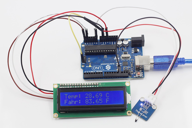
Now, you can see the current value of temperature displayed on the LCD, in both Celsius and Fahrenheit degrees.
