SunFounder Nano Board
Contents
[hide]Overview
The Sunfounder Nano is a small, complete, and breadboard-friendly board based on the ATmega328. It has more or less the same functionality of the Arduino Duemilanove, but in a different package. It lacks only a DC power jack, and works with a Mini-B USB cable instead of a standard one.
Our Nano is fully compatible with Arduino Nano, but the driver of Sunfounder Nano is PL2303
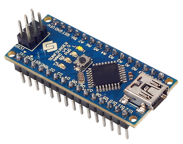
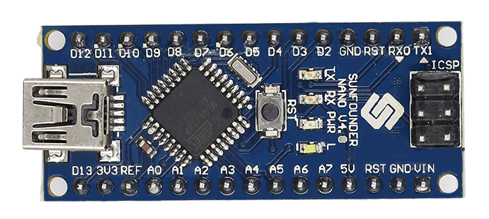
Schematic and Design
Specifications
Microcontroller : ATmega328
Operating Voltage (logic level): 5 V
Input Voltage (recommended): 7-12 V
Input Voltage (limits): 6-20 V
Digital I/O Pins: 14 (of which 6 provide PWM output)
Analog Input Pins: 8
DC Current per I/O Pin: 40 mA
Flash Memory: 32 KB (ATmega328) of which 2 KB used by bootloader
SRAM: 2 KB (ATmega328)
EEPROM: 1 KB (ATmega328)
Clock Speed: 16 MHz
Dimensions: 0.73" x 1.70"
Length: 45 mm
Width: 18 mm
Weigth: 5 g
Power
The Sunfounder Nano can be powered via the Mini-B USB connection, 6-20V unregulated external power supply (pin 30), or 5V regulated external power supply (pin 27). The power source is automatically selected to the highest voltage source.
Input and Output
Each of the 14 digital pins on the Nano can be used as an input or output, using pinMode(), digitalWrite(), and digitalRead() functions. They operate at 5 volts. Each pin can provide or receive a maximum of 40 mA and has an internal pull-up resistor (disconnected by default) of 20-50 kOhms.
In addition, some pins have specialized functions:
Serial: 0 (RX) and 1 (TX):Used to receive (RX) and transmit (TX) TTL serial data. These pins are connected to the corresponding pins of the Prolific USB-to-TTL Serial chip.
External Interrupts: 2 and 3. These pins can be configured to trigger an interrupt on a low value, a rising or falling edge, or a change in value. See the attachInterrupt() function for details.
PWM: 3, 5, 6, 9, 10, and 11. Provide 8-bit PWM output with the analogWrite() function.
SPI: 10 (SS), 11 (MOSI), 12 (MISO), 13 (SCK)'. These pins support SPI communication, which, although provided by the underlying hardware, is not currently included in the Arduino language.
LED: 13. There is a built-in LED connected to digital pin 13. When the pin is HIGH value, the LED is on, when the pin is LOW, it's off.
The Nano has 8 analog inputs, each of which provide 10 bits of resolution (i.e. 1024 different values). By default they measure from ground to 5 volts, though is it possible to change the upper end of their range using the analogReference() function. Analog pins 6 and 7 cannot be used as digital pins. Additionally, some pins have specialized functionality:
I2C: A4 (SDA) and A5 (SCL). Support I2C (TWI) communication using the Wire library (documentation on the Wiring website).
There are a couple of other pins on the board:
AREF: Reference voltage for the analog inputs. Used with analogReference().
Reset: Bring this line LOW to reset the microcontroller. Typically used to add a reset button to shields which block the one on the board.
Communication
The Sunfounder Nano has a number of facilities for communicating with a computer, another Arduino, or other microcontrollers. The ATmega328 provide UART TTL (5V) serial communication, which is available on digital pins 0 (RX) and 1 (TX). An Prolific PL2303TA on the board channels this serial communication over USB and the Prolific PL2303 drivers (included with the Arduino software) provide a virtual com port to software on the computer. The Arduino software includes a serial monitor which allows simple textual data to be sent to and from the Arduino board. The RX and TX LEDs on the board will flash when data is being transmitted via the Prolific chip and USB connection to the computer (but not for serial communication on pins 0 and 1).
A SoftwareSerial library allows for serial communication on any of the Nano's digital pins.
The ATmega328 also support I2C (TWI) and SPI communication. The Arduino software includes a Wire library to simplify use of the I2C bus; see the documentation for details. To use the SPI communication, please see the ATmega168 or ATmega328 datasheet.
Programming
Install Arduino IDE
If you haven't installed the Arduino Integrated Development Environment (IDE) yet, go to https://www.arduino.cc/en/Main/Software.

On the page, check the software list on the right side under Download the Arduino Software. Find the version that suits your operation system and click to download. For the details of installing steps, you can refer to the guide on Installing Arduino IDE.
Install the Driver
The driving chip of our SunFounder Nano board is PL2303TA, different from that of Arduino Nano. So please click the following links to download and install the driver software with the guidance of the PDF files in the package.
PL2303_driver_for_MacOSX![]()
PL2303_driver_for_Microsoft_Windows![]()
When you connect the Nano with the computer via a Mini USB cable, the computer will install the driver automatically. After a while, a prompt message of failed installation will appear. So you need to install it by yourself. Take the steps on Windows.
1) Go to the Device Manager. You will find under Other devices, USB-Serial Controller with an exclamation mark appear, which means the computer did not recognize the Nano board.
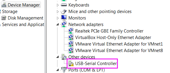
2) Open the PL2303 driver for Microsoft Windows folder and double click to open the PL2303_Prolific_DriverInstaller_v1.12.0.exe file.
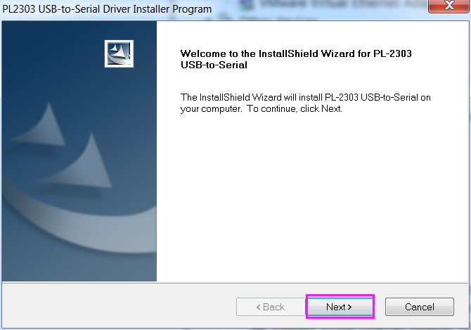
3) The InstallShield Wizard will be displayed to inform you that the PL-2303 USB-to-Serial driver will be installed on your computer. Click Next to continue.
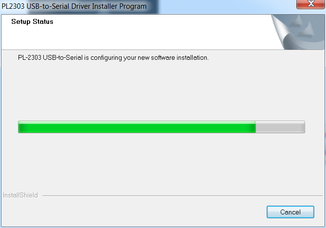
4) The PL-2303 Driver Installer program will then start to install the drivers needed.
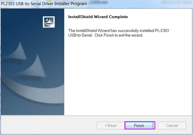
5) Click the Finish button to close the InstallShield program. If you have plugged the cable into the PC while running the setup installation, please unplug and replug the cable for the system to detect the device.
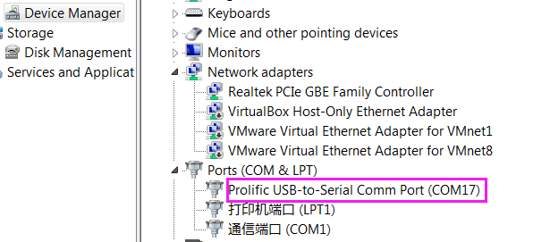
6) Open the Device Manager again and you will find the computer has recognized the Nano at COM17.
Open the IDE
Double click the Arduino icon (arduino.exe) created by the installation process.
Then an empty IDE window will appear. Now open an example sketch (code file) to learn the basics. Select File > Examples >01.Basics > Blink.
Then Tools ->Board->Arduino/Genuino Uno.
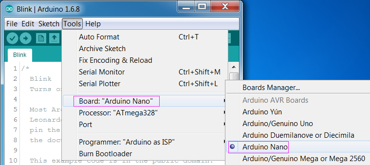
Then select Tools ->Port and select the port you just checked on Device Manager.
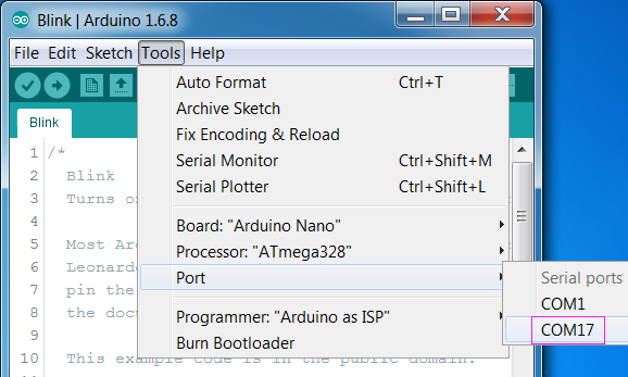
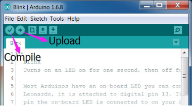
Click the Upload icon to upload the sketch to your board. And the icon Compile to compile sketches (usually used to refer to a code file), which always checks the code. Also when you click Upload, the code will be compiled. The sketches can be uploaded to the board when there is nothing wrong with them. Therefore, generally you just need to click Upload.
If "Done uploading" appears at the bottom of the window, it means the sketch has been successfully uploaded. And if you see the pin 13(L) LED starts to flicker, it means the code has been successfully run.
For more details about Arduino IDE, go to Arduino Software (IDE)
http://www.arduino.cc/en/Guide/Environment
If your sketch fails upload, go to Troubleshooting
