Potentiometer Module
Contents
[hide]overview

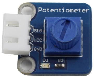
An analog potentiometer is an analog electronic component. What’s the difference between an analog one and a digital one? Simply put, a digital potentiometer refers to just two states like on/off, high/low levels, i.e. either 0 or 1, while a digital one supports analog signals like a number from 1 to 1000. The signal value changes over time instead of keeping an exact number. Analog signals include light intensity, humidity, temperature, and so on.
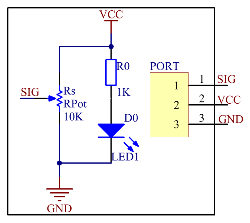
The schematic diagram of the module is as follows:

Rotate the shaft of the potentiometer,then get different resistance which we can use to control the LED flashing time or the brightness of the LED lights
Introduction


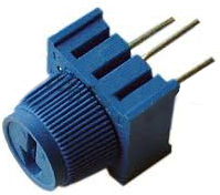
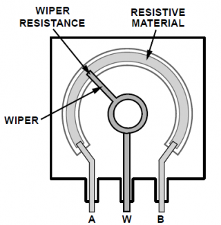
A potentiometer, informally a pot, is a three-terminal resistor with a sliding or rotating contact that forms an adjustable voltage divider.[1] If only two terminals are used, one end and the wiper, it acts as a variable resistor or rheostat.
The measuring instrument called a potentiometer is essentially a voltage divider used for measuring electric potential (voltage); the component is an implementation of the same principle, hence its name.
Potentiometers are commonly used to control electrical devices such as volume controls on audio equipment. Potentiometers operated by a mechanism can be used as position transducers, for example, in a joystick. Potentiometers are rarely used to directly control significant power (more than a watt), since the power dissipated in the potentiometer would be comparable to the power in the controlled load
.
Features
1)A precision potentiometer that is adjustable
2)With an adjustment cap on the potentiometer
3)Working voltage: 5V; PCB size: 2.0 x 2.0 cm
4)adjustable range: 0 - 10K
Application
The module can be used in voltage divider, rheostat, current regulator, etc.
Resource
Test Experiment for Arduino![]()
Test Experiment for Raspberry Pi![]()