Difference between revisions of "MPU6050 Module"
From Wiki
| Line 5: | Line 5: | ||
===Step 1: Connect the circuit=== | ===Step 1: Connect the circuit=== | ||
See the following table for connection between the I2C LCD2004 and the SunFounder Uno board:<br> | See the following table for connection between the I2C LCD2004 and the SunFounder Uno board:<br> | ||
| − | [[File: | + | [[File:Untitled Sketch 2_bb.png]] <br> |
<center> | <center> | ||
{| border="1" class="wikitable" | {| border="1" class="wikitable" | ||
| Line 19: | Line 19: | ||
|- | |- | ||
|align="center"|SDA | |align="center"|SDA | ||
| − | |align="center"|A4 | + | |align="center"|A4 |
|- | |- | ||
|align="center"|SCL | |align="center"|SCL | ||
| − | |align="center"|A5 | + | |align="center"|A5 |
|} | |} | ||
</center> | </center> | ||
Revision as of 01:51, 28 August 2017
Contents
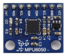
Introduction

The MPU-6050 is the world’s first and only 6-axis motion tracking devices designed for the low power, low cost, and high performance requirements of smartphones, tablets and wearable sensors.
Experimental Procedures
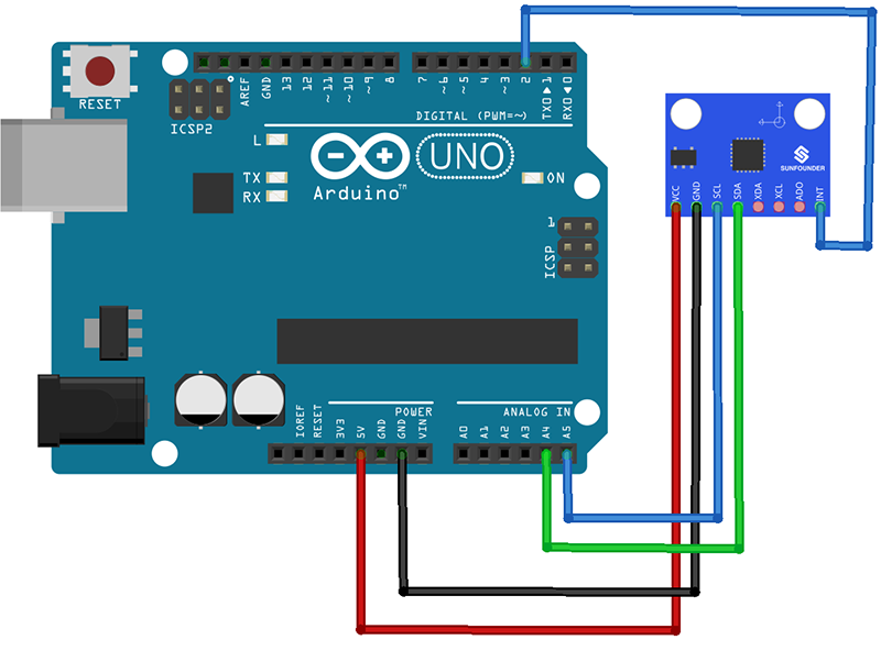
Step 1: Connect the circuit
See the following table for connection between the I2C LCD2004 and the SunFounder Uno board:

| MPU6050 | SunFounder uno Board |
|---|---|
| GND | GND |
| VCC | 5V |
| SDA | A4 |
| SCL | A5 |
Step 2:Add library
Resource
[ Test Experiment for Arduino]![]()
Test Experiment for Raspberry Pi![]()