MPU6050 Module
Contents
[hide]Introduction
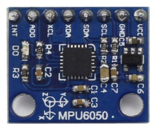
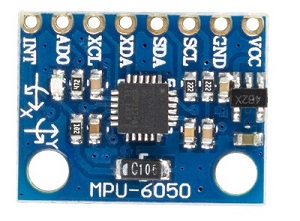
The MPU-6050 is the world’s first and only 6-axis motion tracking devices designed for the low power, low cost, and high performance requirements of smartphones, tablets and wearable sensors.
Experimental Procedures
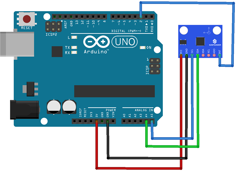
Step 1: Connect the circuit
See the following table for connection between the I2C LCD2004 and the SunFounder Uno board:
| MPU6050 | SunFounder uno Board |
|---|---|
| GND | GND |
| VCC | 5V |
| SDA | A4 |
| SCL | A5 |
| INT | D2 |
Step 2:Add library
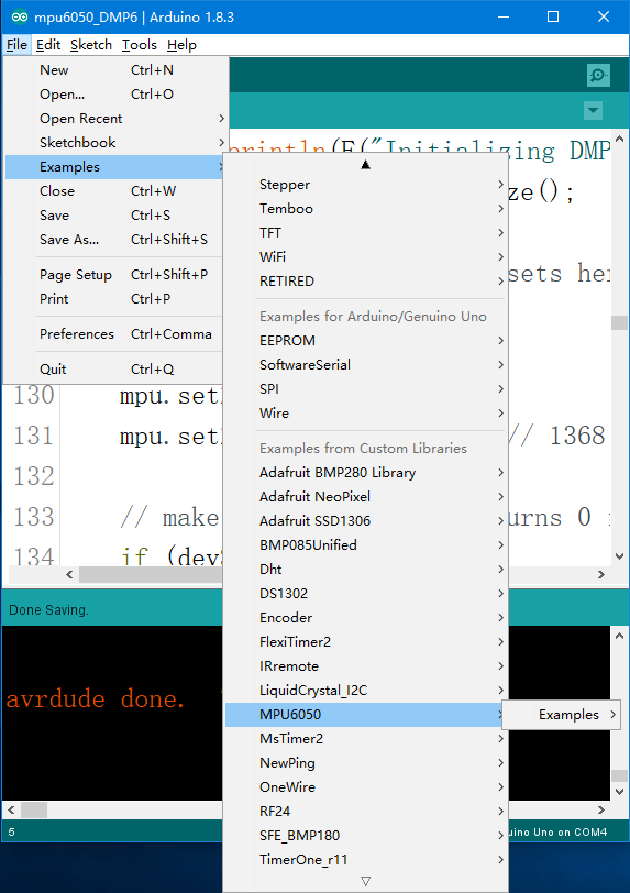
Open Arduino IDE, then click Sketch -> Include Library -> Add ZIP Library, and select MPU6050.zip to include.
After including successfully, you can see the example in File -> Examples -> MPU6050 as shown.
Step 3: Get Drift Compensation Values
The MPU6050 sensor’s reading (raw data) is transformed in space attitude angle. To get more stable and accurate reading, we should set the drift compensation first. The drift differs for different sensors (also affected by environments), thus it’s necessary to configure it before using every time.
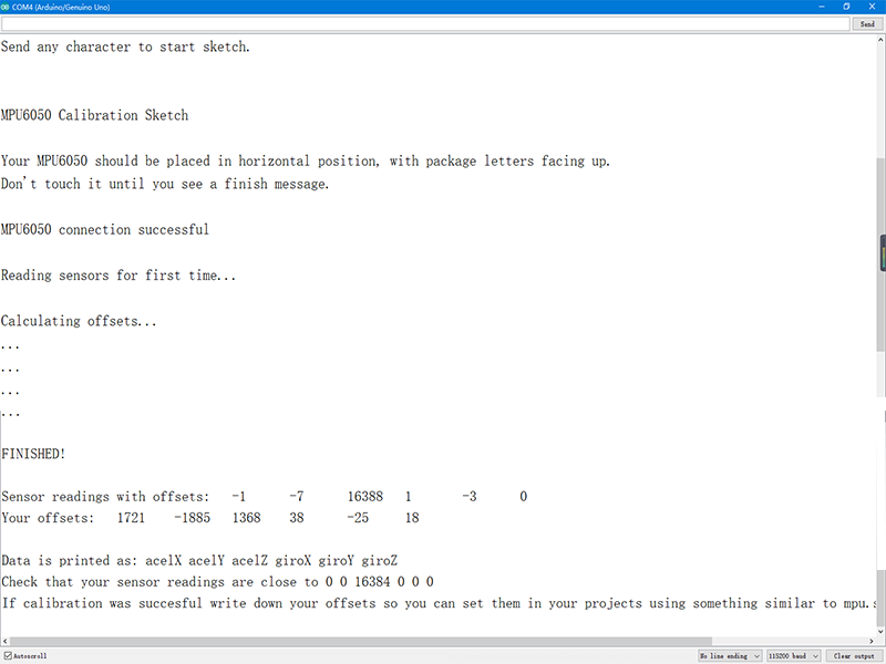
Download mpu6050_calibration in folder examples, select the board type and COM. Open the serial monitor after program uploading, set the baud rate to 115200, and place the MPU6050 horizontally, do not move to avoid any vibration disturbance. Then press any key and click enter. So here you can see the compensation values are 1721, -1885, 1368, 38, -25, and 18, corresponding to six parameters including acceleration (AcceX, AcceY, and AcceZ) and gyroscope (GyroX, GyroY, and GyroZ).
Step 4: Reading Real-time Data
Then go back to the interface of the example mpu6050_DMP6 after including, and go to line 128. Enter the compensation value for “GyroX, GyroY, GyroZ and AcceZ” (as shown in figure below)

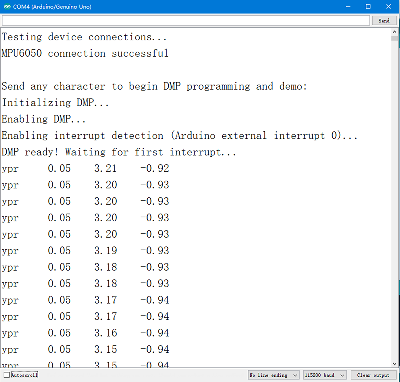
Then upload the program, press any key and click Enter in the serial monitor. Move the MPU6050 and observe the real-time data (as shown in figure below).
Resource
For Arduino Library file download address: MPU_6050.zip![]()
Test Experiment for Raspberry Pi![]()
