DS1307
DESCRIPTION
The DS1307 Serial Real-Time Clock is a low-power, full binary-coded decimal (BCD) clock/calendar plus 56 bytes of NV SRAM. Address and data are transferred serially via a 2-wire, bi-directional bus. The clock/calendar provides seconds, minutes, hours, day, date, month, and year information. The end of the month date is automatically adjusted for months with fewer than 31 days, including corrections for leap year. The clock operates in either the 24-hour or 12-hour format with AM/PM indicator. The DS1307 has a built-in power sense circuit that detects power failures and automatically switches to the battery supply.
FEATURES
- Real-time clock (RTC) counts seconds, minutes, hours, date of the month, month, day of the week, and year with leap-year compensation valid up to 2100 *56-byte, battery-backed, nonvolatile (NV) RAM for data storage *Two-wire serial interface *Programmable squarewave output signal *Automatic power-fail detect and switch circuitry * Consumes less than 500nA in battery backup mode with oscillator running *Optional industrial temperature range: -40°C to +85°C * Available in 8-pin DIP or SOIC *Underwriters Laboratory (UL) recognized
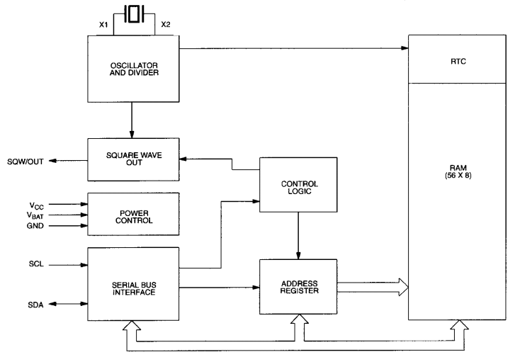
DS1307 BLOCK DIAGRAM
Pin Function

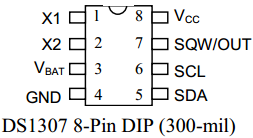
VCC, GND
DC power is provided to the device on these pins. VCC is the +5V input. When 5V is applied within normal limits, the device is fully accessible and data can be written and read. When a 3V battery is connected to the device and VCC is below 1.25 x VBAT, reads and writes are inhibited. However, the timekeeping function continues unaffected by the lower input voltage. As VCC falls below VBAT the RAM and timekeeper are switched over to the external power supply (nominal 3.0V DC) at VBAT.
VBAT
Battery input for any standard 3V lithium cell or other energy source. Battery voltage must be held between 2.0V and 3.5V for proper operation. The nominal write protect trip point voltage at which access to the RTC and user RAM is denied is set by the internal circuitry as 1.25 x VBAT nominal. A lithium battery with 48mAhr or greater will back up the DS1307 for more than 10 years in the absence of power at 25ºC. UL recognized to ensure against reverse charging current when used in conjunction with a lithium battery.
SCL (Serial Clock Input)
SCL is used to synchronize data movement on the serial interface.
SDA (Serial Data Input/Output)
SDA is the input/output pin for the 2-wire serial interface. The SDA pin is open drain which requires an external pullup resistor.
SQW/OUT (Square Wave/Output Driver)
When enabled, the SQWE bit set to 1, the SQW/OUT pin outputs one of four square wave frequencies (1Hz, 4kHz, 8kHz, 32kHz). The SQW/OUT pin is open drain and requires an external pull-up resistor. SQW/OUT will operate with either Vcc or Vbat applied.
X1, X2
Connections for a standard 32.768kHz quartz crystal. The internal oscillator circuitry is designed for operation with a crystal having a specified load capacitance (CL) of 12.5pF
.
