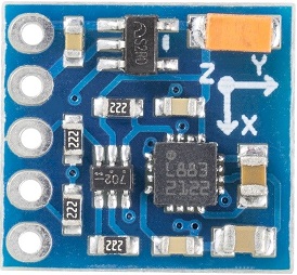
GY-271 HMC5883L 3-Axis Magnetic Electronic Compass Module
Contents
Introduction

The Compass Module is designed for low-field magnetic sensing with a digital interface and perfect to give precise heading information. This compact sensor fits into small projects such as UAVs and robot navigation systems. The sensor converts any magnetic field to a differential voltage output on 3 axes. This voltage shift is the raw digital output value, which can then be used to calculate headings or sense magnetic fields coming from different directions.
Main Features
- Gold plating PCB, applying machine welding technology, superb technique and reliably quality guarantee!
- Name: HMC5883L Module (Triaxial Magnetic Field Module);
- Type: GY-271;
- Used Chip: HMC5883L;
- Power Supply: 3~5V;
- Communication Mode: Standard IIC communicating protocol;
- Measuring Range: ±1.3-8 Gauss.
Introduction of Pins
| Pin Introduction | |
|---|---|
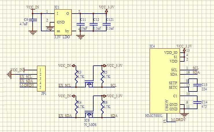
| VCC | Connected to the anode of the power supply (3~5v) |
| GND | Connected to the cathode of the power supply |
| SCL | I²C clock |
| SDA | I²C data |
| DRDY | Interrupting pin for data preparation, DRDY is pulled up inside and keeps the low level for 250μsec when the data are on the output register. |
Principle
Honeywell HMC5883L is a kind of SMT High integration module that has a weakly magnetic sensor chip with digital interface. It is widely used in testing of low cost compass and magnetic field. HMC5883L contains the latest high resolution HMC118X series magnetoresistive sensor and Honeywell-patent integrated circuit including amplifier, automatic demagnetization driver, deviation calibration and 12-bit A/D converter that can keep the precision of compass ranging within 1°~2°. What’s more, it has simply equipped I2C series bus interfaces.
Experimental Procedures for Arduino
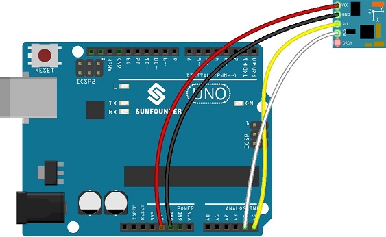
| GY-271 | Arduino uno |
| VCC | VCC |
| GND | GND |
| SCL | A5 |
| SDA | A4 |
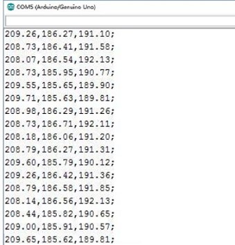
The serial monitor shows the results (X plane angle, Y plane angle, Z plane angle in degrees) of different positions of the module.
Step 2: Compile and upload the code.
#include <Wire.h>
#include <HMC5883L.h>
HMC5883L compass;
void setup()
{
 Serial.begin(9600);
 Wire.begin();
 compass = HMC5883L();
 compass.SetScale(1.3);
 compass.SetMeasurementMode(Measurement_Continuous);
}
void loop()
{
 MagnetometerRaw raw = compass.ReadRawAxis();
 MagnetometerScaled scaled = compass.ReadScaledAxis();
 float xHeading = atan2(scaled.YAxis, scaled.XAxis);
 float yHeading = atan2(scaled.ZAxis, scaled.XAxis);
 float zHeading = atan2(scaled.ZAxis, scaled.YAxis);
 if(xHeading < 0) xHeading += 2*PI;
 if(xHeading > 2*PI) xHeading -= 2*PI;
 if(yHeading < 0) yHeading += 2*PI;
 if(yHeading > 2*PI) yHeading -= 2*PI;
 if(zHeading < 0) zHeading += 2*PI;
 if(zHeading > 2*PI) zHeading -= 2*PI;
 float xDegrees = xHeading * 180/M_PI;
 float yDegrees = yHeading * 180/M_PI;
 float zDegrees = zHeading * 180/M_PI;
 Serial.print(xDegrees);
 Serial.print(",");
 Serial.print(yDegrees);
 Serial.print(",");
 Serial.print(zDegrees);
 Serial.println(";");
 delay(100);
}
The serial monitor shows the results (X plane angle, Y plane angle, Z plane angle in degrees) of different positions of the module.


