Difference between revisions of "SF2205 Motor + 20A ESC Power Kit"
(→SF2205Brushless Motors) |
(→Features) |
||
| (6 intermediate revisions by the same user not shown) | |||
| Line 22: | Line 22: | ||
|2300 | |2300 | ||
|1024g | |1024g | ||
| − | |31.7 MM | + | |31.7 MM |
| + | |3~4S | ||
| + | |30g | ||
| + | |12N14P | ||
| + | |3 MM | ||
|HQ5045 BN | |HQ5045 BN | ||
|27.9 MM | |27.9 MM | ||
|} | |} | ||
| − | |||
| − | |||
| − | |||
| − | |||
| − | |||
| − | |||
| − | |||
| − | |||
| − | |||
| − | |||
[[File:MG 1484.jpg]]<br> | [[File:MG 1484.jpg]]<br> | ||
| Line 47: | Line 41: | ||
6. The twisted-pair design of the throttle signal cable effectively reduces the crosstalk generatedin signal transmission and makes the flight more stable.<br> | 6. The twisted-pair design of the throttle signal cable effectively reduces the crosstalk generatedin signal transmission and makes the flight more stable.<br> | ||
7. Works with various flight controllers and supports a signal frequency of up to 621MHz in "Regular" signal-receiving mode.<br> | 7. Works with various flight controllers and supports a signal frequency of up to 621MHz in "Regular" signal-receiving mode.<br> | ||
| − | + | ||
| − | + | Specifications:: | |
| − | + | {| border="1" class="wikitable" style="text-align: center;" | |
| − | + | |- | |
| − | + | | Input | |
| − | + | | Constant | |
| − | + | | Burst | |
| − | + | | Weight | |
| − | + | | Dimensions | |
| − | + | | Motor wire | |
| − | + | | Signal wire | |
| + | | PCB | ||
| + | | Mosfet | ||
| + | |- | ||
| + | |2-4s Lipo | ||
| + | |20Amps | ||
| + | |30Amps | ||
| + | |6g (bare board) | ||
| + | |23.8x14.5x5.8mm | ||
| + | |100mm | ||
| + | |155mm | ||
| + | |4 layer blind hole, 3oz pour | ||
| + | |N-Channel | ||
| + | |} | ||
| + | |||
| + | ==Features== | ||
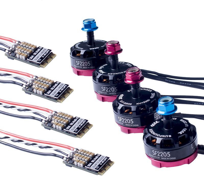
| + | *Includes 2 pairs of SF2205CW and CCW brushless motors and 4 pieces of 20A ESCs for 180, 210, and 250 RCmultirotors | ||
| + | *SF2205 2300KV brushless motors: uniquestrong inflowdesign for quick cooling, low gravity center for more stable flight, and lightweight for longer flight time | ||
| + | *CWand CCW mark on the motor for quick recognition and thus easy assembly;double anti-loose flange nuts for firmly fixing props in high-speed exciting flight | ||
| + | *The 20A ESCsapply the BLHeli-Sopen source program, all its functions supported; small and light weight, easy to install | ||
| + | *The ESC works wellwith various flight-controllers and supports common throttle modes of PWM, OneShot125,OneShot42,and MultiShot | ||
==Operations== | ==Operations== | ||
Latest revision as of 02:45, 27 May 2017
Contents
Introduction
SF2205Brushless Motors
1. Unique strong inflow design cools the motor during flight, thus enhancing efficiency.
2. Low gravity center reduces frame shakes due to motor spinning, enabling more stable flight.
3. Clear CW and CCW markson the motormake it easy to recognizeand assemble.
4. Double anti-loose flange nuts are used for firmly fixing propellersin high-speed exciting flight.
5. It is light weight thus providing longer flight time.
Specifications::
| KV | Max. Thrust | Length | No.of CELL | Weight | Framework | Shaft diameter | Propellermodel | Motor diameter |
| 2300 | 1024g | 31.7 MM | 3~4S | 30g | 12N14P | 3 MM | HQ5045 BN | 27.9 MM |
20A BLHeli-S ESC
1. Adopts EMF8BB2 chip for powerful performance with an operation frequency of 48MHz
2. The BLHeli-Sopen-source program implemented in the ESC supports all BLHeli-S functionslike ESC programming andfirmware upgrade via the throttle control signal cable.
3. Small size andlight weight for easy installation
4. Freewheeling-alike damped light modebringsfastmotor response.
5. Supports regular 1-2ms pulse width input, as well as Oneshot125(125-250us), Oneshot42(41.7-83.3us),and Multishot (5-25us); the input signal is automatically detected by the ESC upon power up.
6. The twisted-pair design of the throttle signal cable effectively reduces the crosstalk generatedin signal transmission and makes the flight more stable.
7. Works with various flight controllers and supports a signal frequency of up to 621MHz in "Regular" signal-receiving mode.
Specifications::
| Input | Constant | Burst | Weight | Dimensions | Motor wire | Signal wire | PCB | Mosfet |
| 2-4s Lipo | 20Amps | 30Amps | 6g (bare board) | 23.8x14.5x5.8mm | 100mm | 155mm | 4 layer blind hole, 3oz pour | N-Channel |
Features
- Includes 2 pairs of SF2205CW and CCW brushless motors and 4 pieces of 20A ESCs for 180, 210, and 250 RCmultirotors
- SF2205 2300KV brushless motors: uniquestrong inflowdesign for quick cooling, low gravity center for more stable flight, and lightweight for longer flight time
- CWand CCW mark on the motor for quick recognition and thus easy assembly;double anti-loose flange nuts for firmly fixing props in high-speed exciting flight
- The 20A ESCsapply the BLHeli-Sopen source program, all its functions supported; small and light weight, easy to install
- The ESC works wellwith various flight-controllers and supports common throttle modes of PWM, OneShot125,OneShot42,and MultiShot
Operations
1. Assembly of the quadcopter (DO NOT assemble the propellers now for safety reason)
Soldering of the ESCs:
https://www.youtube.com/watch?v=RVhLOXCg7vY
Motor soldering + flight control mounting
https://www.youtube.com/watch?v=LCHJD7Bug9U
Whole assembly:
https://www.youtube.com/watch?v=AT-HOwGvYio
2. Installing CleanFlight
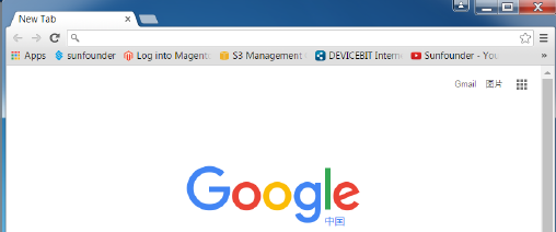
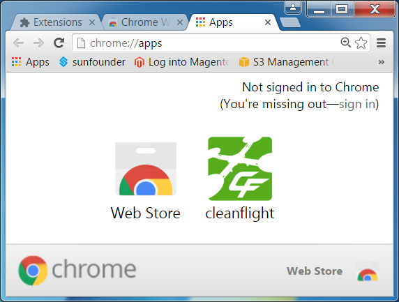
Run the Google Chrome
You will see the interface like the below:
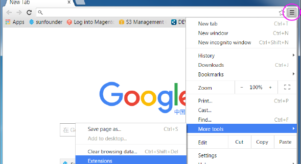
Click on the Customize and Control Google Chrome button at the top right of the window, and then on the drop-down list select More Tools -> Extensions.
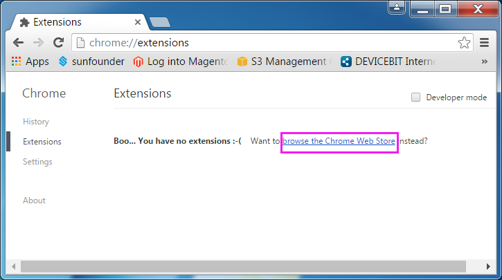
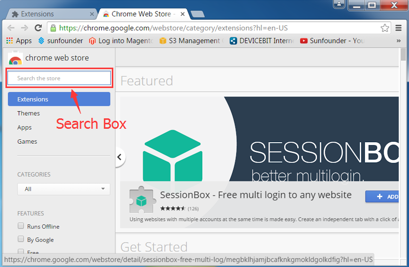
Click browse the Chrome Web Store.
Click Get more extensions and you will see the interface below:
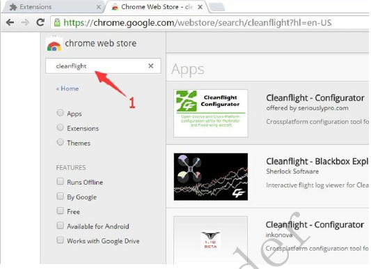
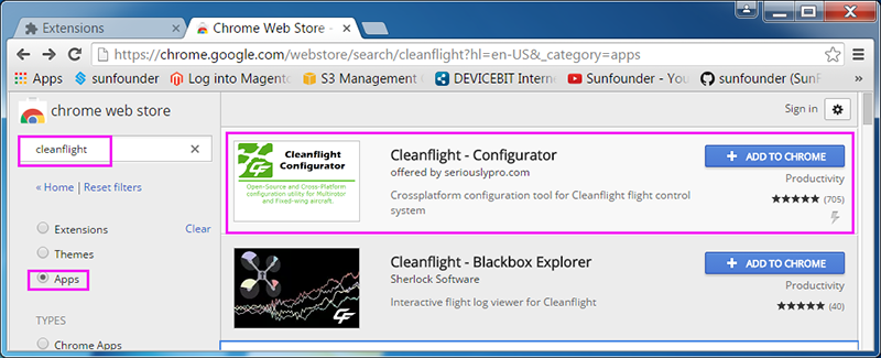
Input CleanFlight in the search box in the top left corner to search for the firmware and the results will be shown as below:
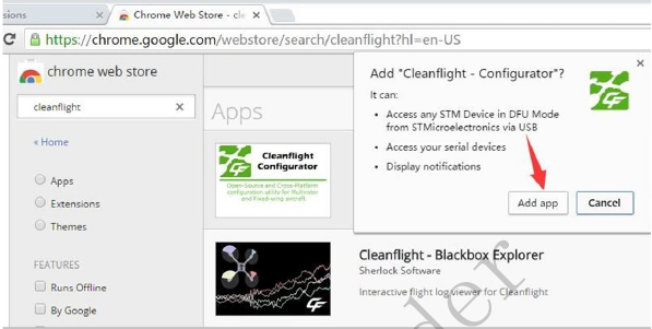
Click + ADD TO CHROME to add the plug-in to the Google Chrome. There will be a prompt then; just click Add app.
Wait for a while till it is loaded successfully and the CleanFlight icon will appear on the interface.
3. Flashing the SPRACING F3 Firmware
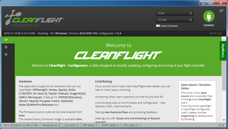
Click CleanFlight to run the ground station software.
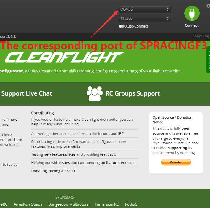
Connect the flight controller with the computer via a USB cable. Open the Device Manager on your computer and see whether the flight controller has been recognized. If yes, heck the COM port number. Choose the corresponding COM port in the top right corner of the firmware. But do not click the Connect button now.
If no driver is found for the device, please install it first.
You can download the driver in this website:
http://www.silabs.com/products/mcu/pages/usbtouartbridgevcpdrivers
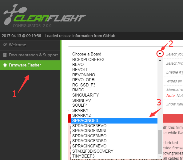
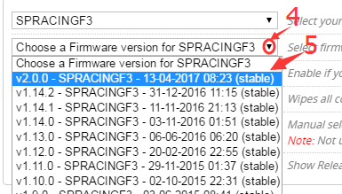
Click Firmware Flasher to upgrade and flash the firmware. Now click the triangle next to Choose a Board on the page, and on the drop-down list select SPRACINGF3. Then click Choose a Firmware version for SPRACINGF3 on the page, and on the drop-down list select the lastest firmware for the flight controller.
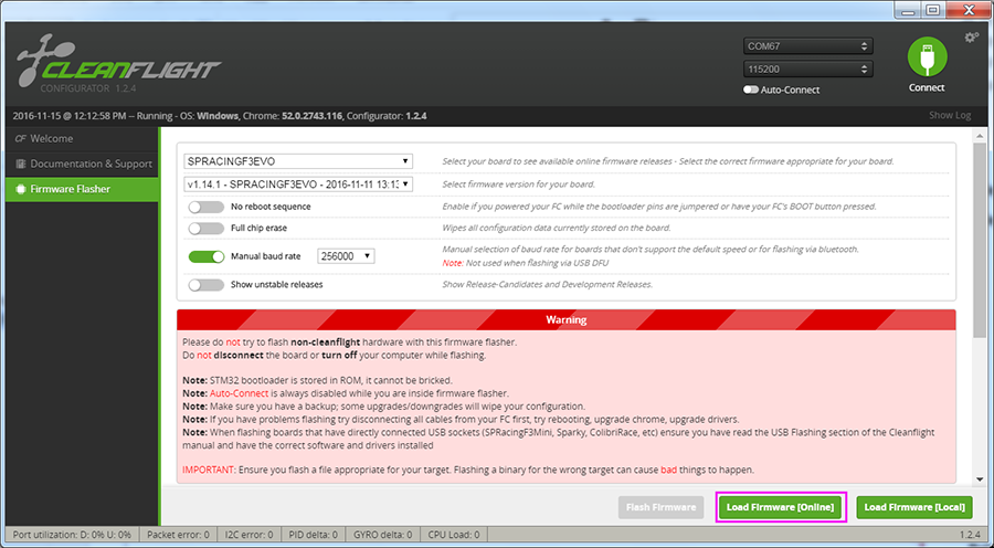
Click Load Firmware(Online) to load the firmware (if you happen to have downloaded the firmware before, you can choose Load Firmware(Local)).
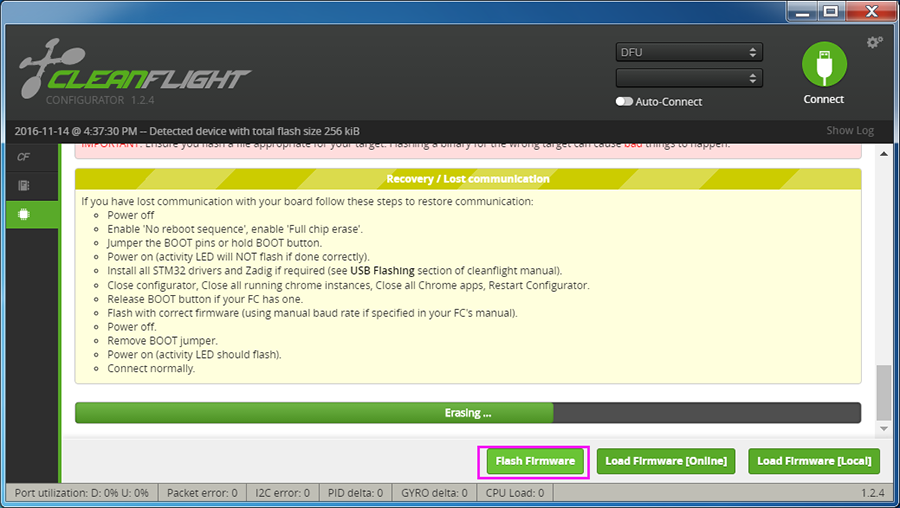
After loading, click Flash Firmware to flash the firmware.
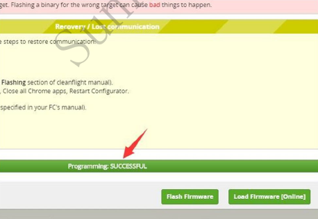
If flashing is done successfully, you will see the interface below:
So the firmware has been upgraded successfully.
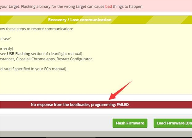
But sometimes failures may occur when you flash the firmware, like as below:
In that case, we need to use another method to flash the firmware, using FlyMcu tools and the latest hex file.
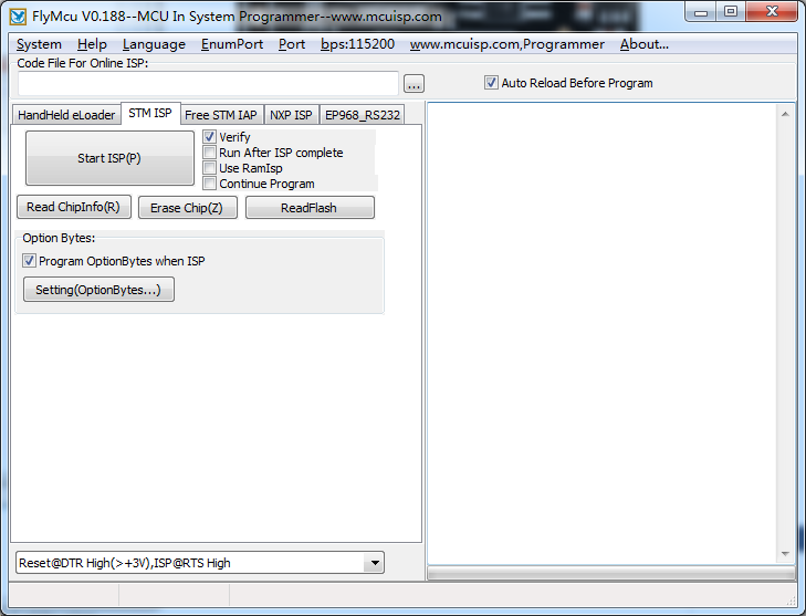
FlyMcu![]()
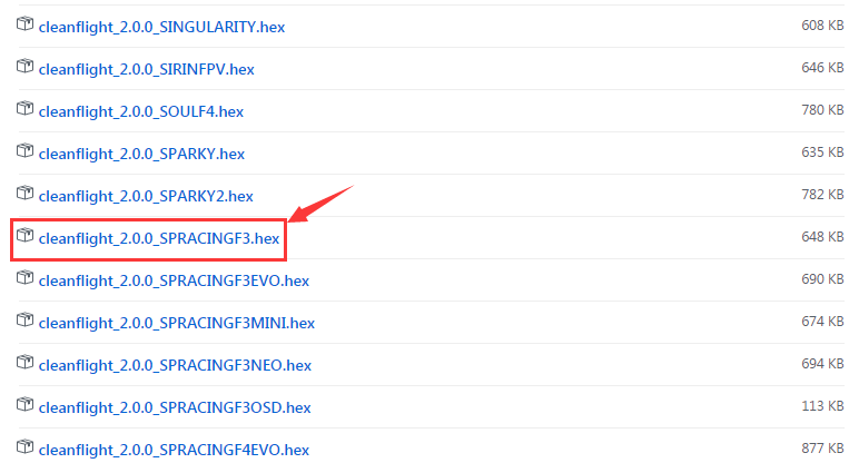
Download the hex file of cleanflight for your flight controller on this page:
https://github.com/cleanflight/cleanflight/releases
Then take the following steps:
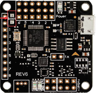
1) Connect the two pads labeled with boot by soldering on the flight controller.
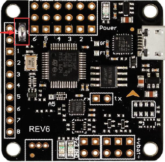
The flight controller after soldering will be like this:
2) Open mcuisp and plug the USB cable. REMEMBER to plug in only when boot’s connected.
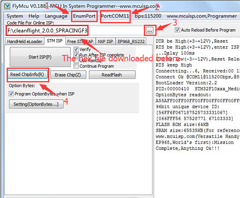
3) Click the Port: COM1 in the menu bar and click EnumPort to search for the port, then select the port for your device. Click the button next to the text box under Code File For Online ISP: and find the hex file downloaded. Then click Read ChipInfo, and the information of the chip will be showed on the right box.
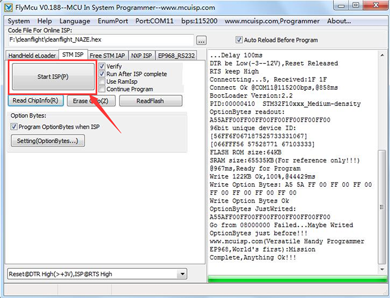
4) Click Start ISP(P) and wait until “Anything Ok” appears at the bottom. Disconnect the USB cable and remove the solder in the boot on the board. Now the problem has been repaired.
4. BLHeliSuite
BLHeliSuite![]()
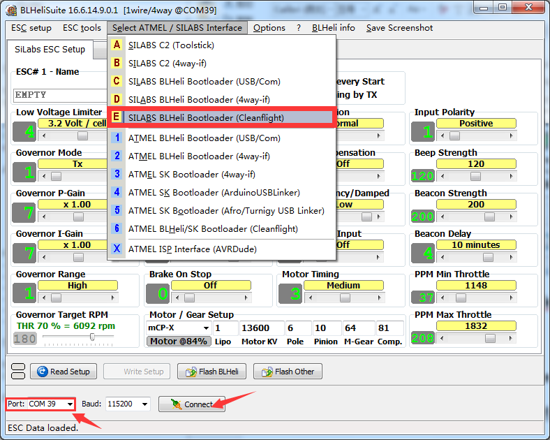
Connect the flight control and the PC with a USB cable. Make sure it is connected to the CleanFlight, and then run the BLHeli. Click Select ATMEL / SILABS Interface -> E SILABS BLHeli Bootloader(Cleanflight). Note that the port should be the same with the COM port in CleanFlight, like COM 39 as shown below:
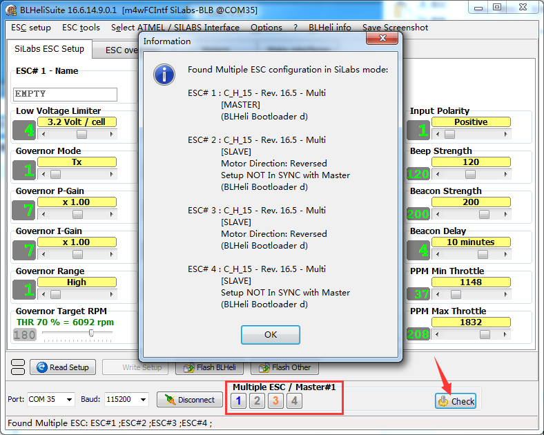
Click Connect. After the connection is done successfully, mount the battery to power on the drone and click Check. Then a window will pop up to prompt you the version of the 4 ESCs.
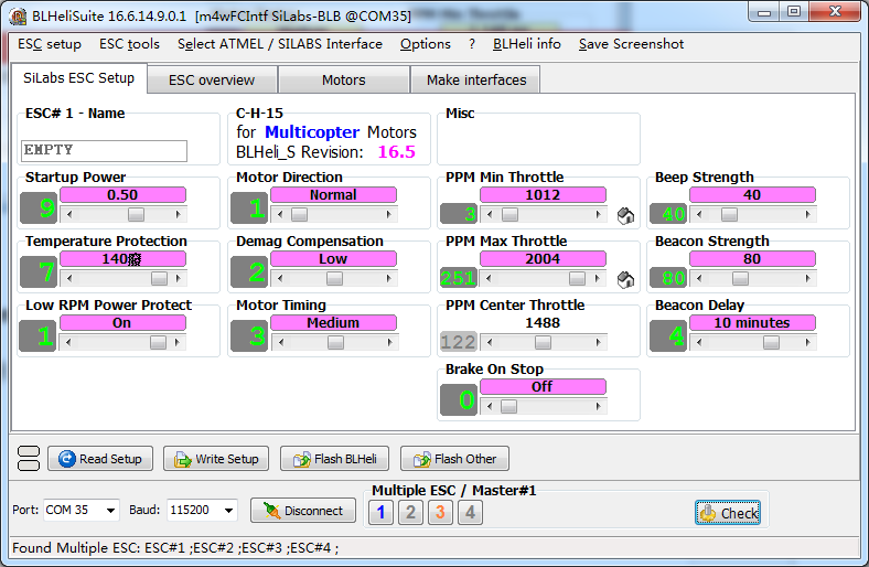
Click OK and the interface will change.
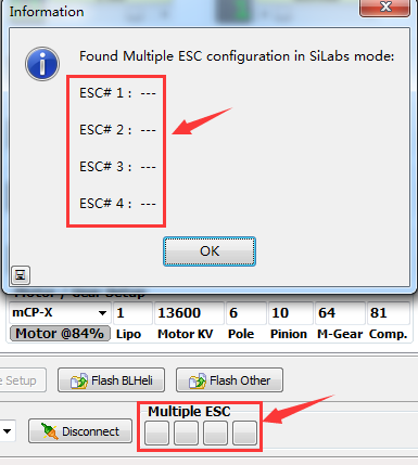
If the version information is null after you click Check, take the following steps: exit the BLHeli software -> remove the battery -> unplug the USB cable -> connect the battery -> re-plug the USB cable -> open the BLHeli software. Then all the ESCs should be recognized.
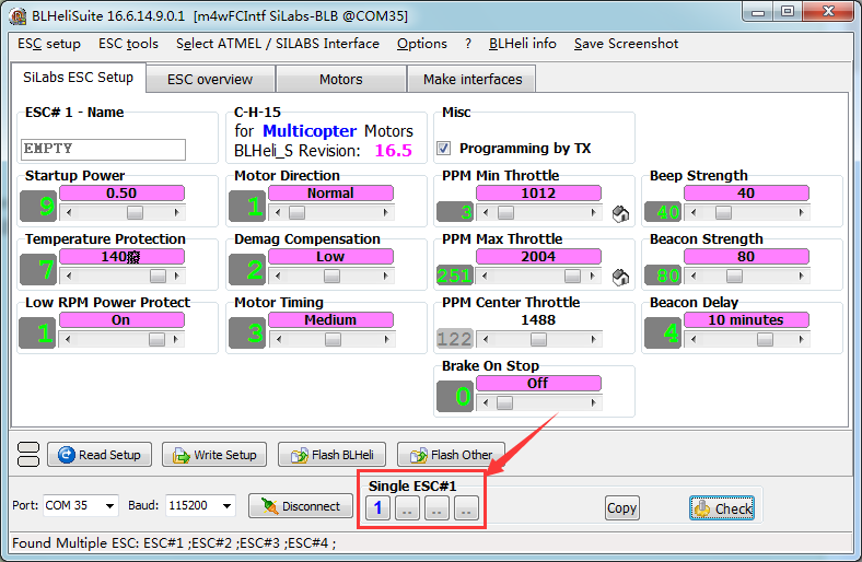
You can click to select the ESC to be debugged. For example, to select only No. 1 ESC, click the 2, 3, and 4 to close them, as shown below. If you select more than one ESC at the same time, it means you want to debug them at one time. Note: The No.1, 2, 3, and 4 corresponding to the No. 1-4 ESCs in the CleanFlight.
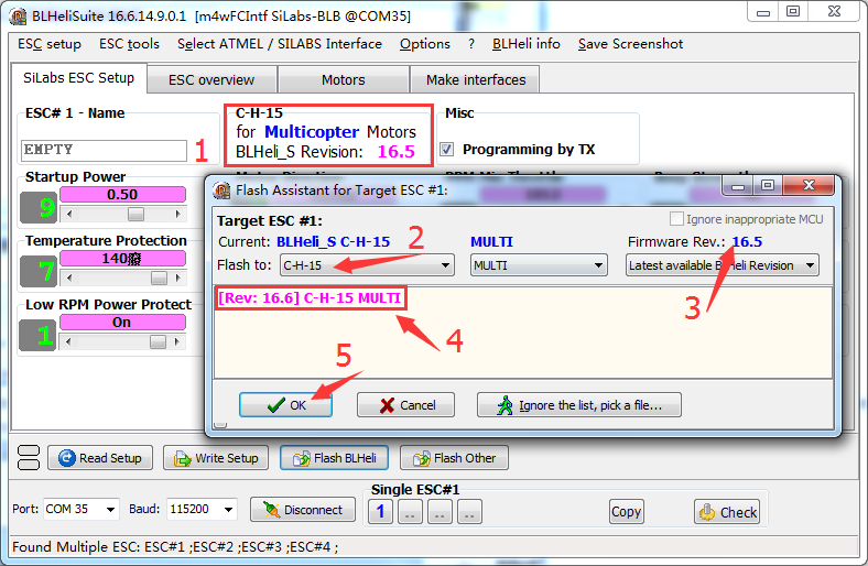
Click Flash BLHeli and the window for firmware selection will pop up. If the ESC's brand and model have been recognized, the program will show the latest firmware list for your selection, as shown below:
Let's take an example for flashing the firmware to the No.1 ESC. For the rest 3 ESCs, the method is the same. Click the firmware needed, click OK, and a window will pop up prompting you to confirm the firmware again. Click Yes to start flashing.
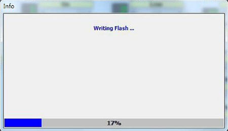
After the progress bar goes to the end, the firmware has been flashed to the first ESC.
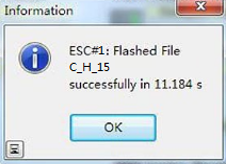
Then a window will be prompted to show you the time of the flashing.
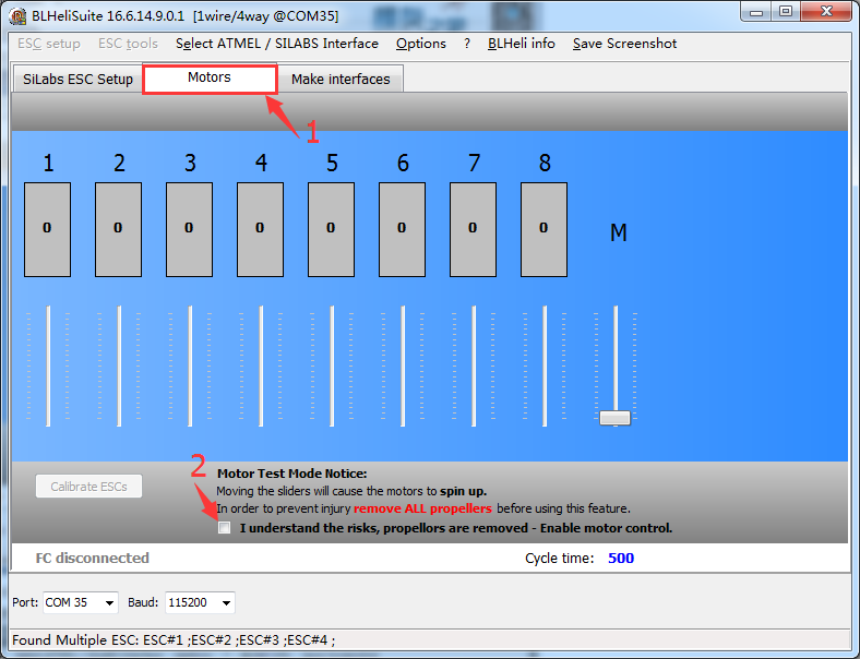
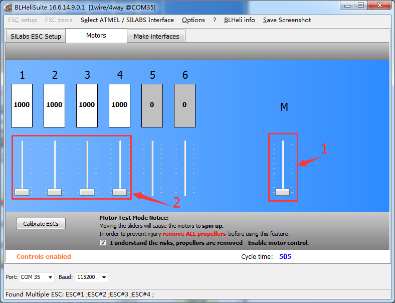
A few seconds later, after the software finishes flashing the firmware to the ESC, the ESC will reboot. Then the window comes to Motors, click "I understand the risks…."
Slightly pull the M bar when observing whether the 4 motors spin normally. Then click the 1-4 sliders one by one at the left and check whether the motors rotate well respectively.
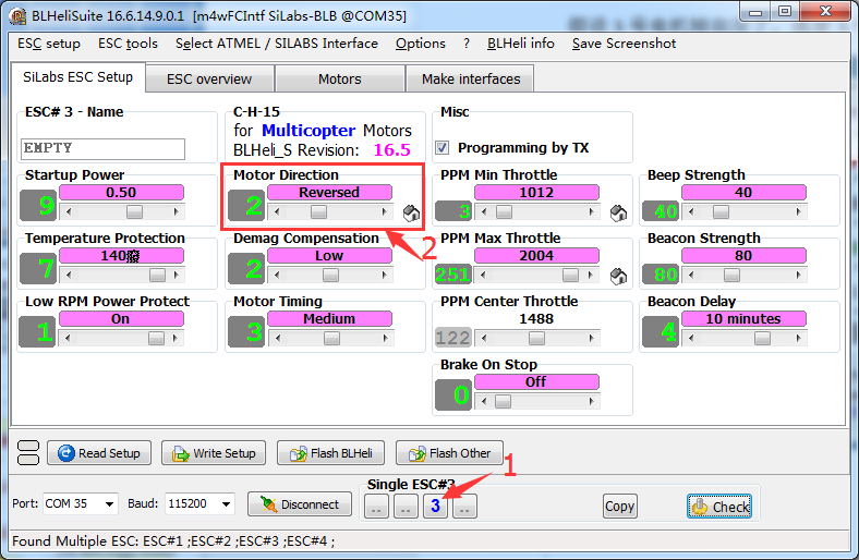
Assume that the No.3 motor is spinning reversely. Click to select 3, pull the slider under Motor Direction and the direction will be reversed. This is convenient and quick to change a motor's direction needless to changing the wiring between the motor and ESC.
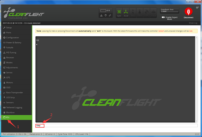
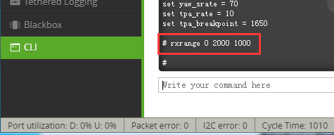
Surely you can readjust the motor on the CLI (command line interface) of CleanFlight or BetaFlight.
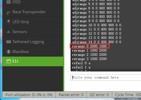
For example, if Roll is reversed, type in dump:
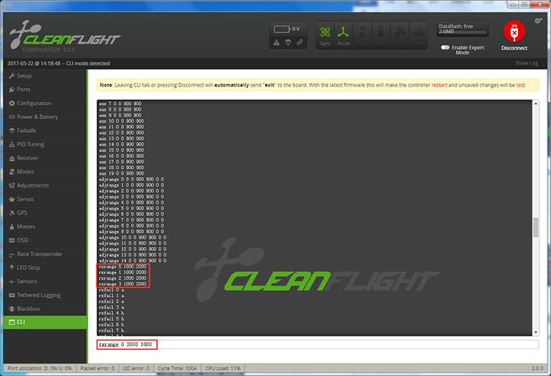
And the rxrange data will be printed. Modify the rxrange 0 1000 2000 (meaning, min: 1000, max: 2000), like exchanging the two, press Enter.
Now you can see the min and max values of the rxrange 0 are exchanged, which means the direction of the motor is reversed then.
Type in dump again, and then you will see rxrange 0 is changed. Type in save to save the data.
In this line, the first number x of "rxrange x xxxx xxxx" is mapped to Roll, Pitch, Yaw, and Throttle respectively.
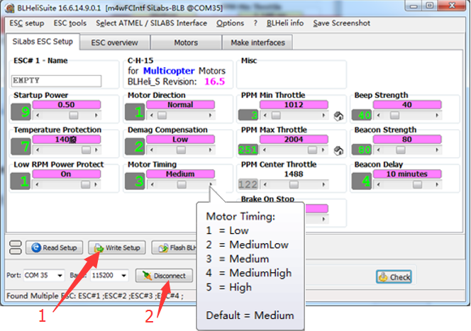
Motor Timing
As for the motor timing and other settings, you can explore by yourself. It would be a little challenging and you can post your questions if you can't figure it out after researching.
After settings are all done for the ESCs, click Write Setup at the bottom. Then the software will write the settings to the corresponding ESC. Click Disconnect to break with the COM port, and now you can take the unlock test. For detailed operations, please refer to the chapter 3. Test the SFX190 (Assembled) in the SF250 Assembled Kit Components Test Before Assembly WIKI page.
So, that's all for the debugging. With these instructions you should be able to apply the quadcopter well. Now go get some fun with the kit!
