Difference between revisions of "Relay(LOW) for Arduino"
(Created page with "=='''Introduction'''== File:Relay1.jpg Relays are suitable for driving high power electronic devices such as lights, electric fans and air condition. A relay can be used...") |
(→Resorce) |
||
| (7 intermediate revisions by the same user not shown) | |||
| Line 1: | Line 1: | ||
=='''Introduction'''== | =='''Introduction'''== | ||
| − | [[File:Relay1.jpg]] | + | [[File:Relay1.jpg]]<br> |
Relays are suitable for driving high power electronic devices such as lights, electric fans and air condition. A relay can be used to control high voltages with a low voltage by connecting it to an MCU.<br> | Relays are suitable for driving high power electronic devices such as lights, electric fans and air condition. A relay can be used to control high voltages with a low voltage by connecting it to an MCU.<br> | ||
The schematic diagram of the module is as follows:<br> | The schematic diagram of the module is as follows:<br> | ||
| − | [[File:Relay2.png]] | + | [[File:Relay2.png]]<br> |
Sending a low level to SIG; the PNP transistor is energized and the coil of the relay is electrified. Thus, the normally open contact of the relay is closed, while the normally closed contact of the relay will be open. Send a high level to SIG; the transistor will be de-energized and the relay will restore to the initial state.<br> | Sending a low level to SIG; the PNP transistor is energized and the coil of the relay is electrified. Thus, the normally open contact of the relay is closed, while the normally closed contact of the relay will be open. Send a high level to SIG; the transistor will be de-energized and the relay will restore to the initial state.<br> | ||
| + | |||
=='''Principle of relay'''== | =='''Principle of relay'''== | ||
See the picture here :A is an electromagnet, B armature, C spring, D moving contact, and E fixed contacts. There are two fixed contacts, a normally closed and a normally open. When the coil is not energized, the normally open contact is the one that is off, while the normally closed one is the other that is on. <br> | See the picture here :A is an electromagnet, B armature, C spring, D moving contact, and E fixed contacts. There are two fixed contacts, a normally closed and a normally open. When the coil is not energized, the normally open contact is the one that is off, while the normally closed one is the other that is on. <br> | ||
| − | [[File:Relay3.png]] | + | [[File:Relay3.png]]<br> |
Add a certain voltage to the coil and some currents will pass through the coil thus generating the electromagnetic effect. So the armature overcomes the tension of the spring and is attracted to the core, thus closing the moving contact of the armature and the normally open contact (or you may say releasing the former and the normally closed contact). After the coil is deenergized, the electromagnetic force disappears and the armature moves back to the original position, releasing the moving contact and normally closed contact. The closing and releasing of the contacts results in power on and off of the circuit.<br> | Add a certain voltage to the coil and some currents will pass through the coil thus generating the electromagnetic effect. So the armature overcomes the tension of the spring and is attracted to the core, thus closing the moving contact of the armature and the normally open contact (or you may say releasing the former and the normally closed contact). After the coil is deenergized, the electromagnetic force disappears and the armature moves back to the original position, releasing the moving contact and normally closed contact. The closing and releasing of the contacts results in power on and off of the circuit.<br> | ||
| + | |||
=='''Features'''== | =='''Features'''== | ||
1)Support control of DC and AC signals (AC 220V load)<br> | 1)Support control of DC and AC signals (AC 220V load)<br> | ||
| Line 16: | Line 18: | ||
The module can be used as a development module on an MCU or for control of household appliances.<br> | The module can be used as a development module on an MCU or for control of household appliances.<br> | ||
=='''Resorce'''== | =='''Resorce'''== | ||
| − | [http:// | + | [http://wiki.sunfounder.cc/images/1/1f/Relay_datasheet.pdf Relay_datasheet] [[File:PDF.jpg]]<br> |
| + | [https://www.sunfounder.com/learn/Sensor-Kit-v2-0-for-Arduino/lesson-19-relay-sensor-kit-v2-0-for-arduino.html Test Experiment for Arduino][[File:LINK.jpg]] | ||
Latest revision as of 07:26, 20 March 2017
Introduction

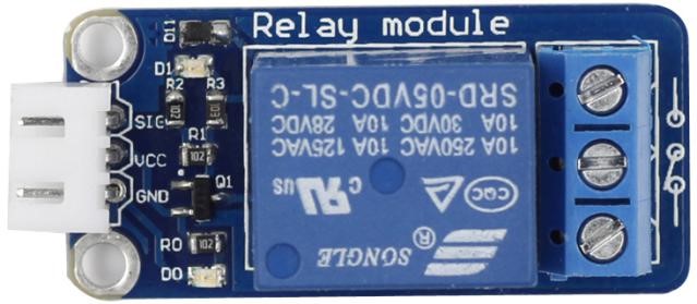
Relays are suitable for driving high power electronic devices such as lights, electric fans and air condition. A relay can be used to control high voltages with a low voltage by connecting it to an MCU.
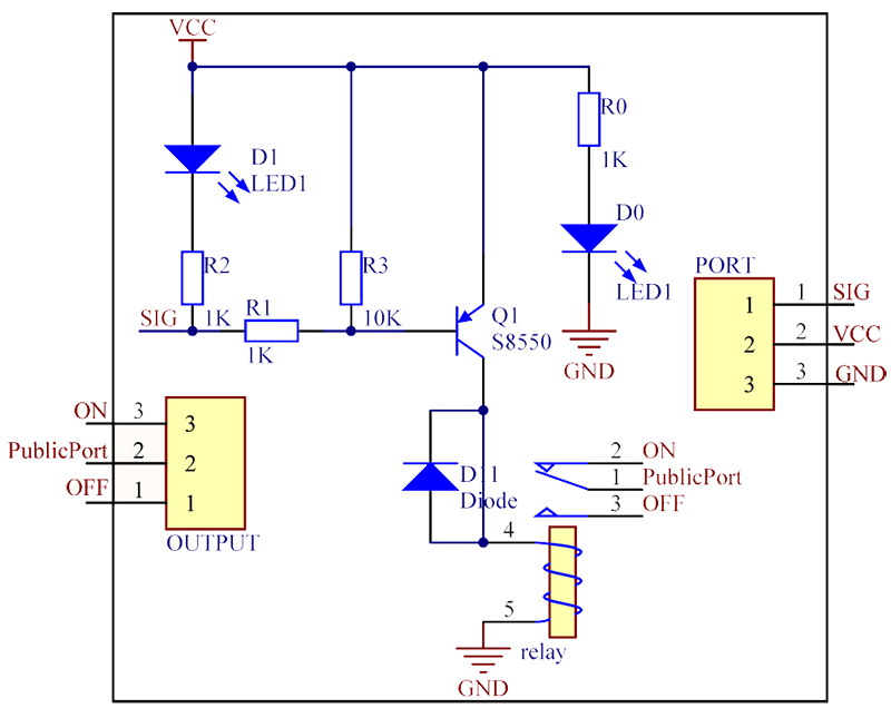
The schematic diagram of the module is as follows:

Sending a low level to SIG; the PNP transistor is energized and the coil of the relay is electrified. Thus, the normally open contact of the relay is closed, while the normally closed contact of the relay will be open. Send a high level to SIG; the transistor will be de-energized and the relay will restore to the initial state.
Principle of relay
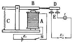
See the picture here :A is an electromagnet, B armature, C spring, D moving contact, and E fixed contacts. There are two fixed contacts, a normally closed and a normally open. When the coil is not energized, the normally open contact is the one that is off, while the normally closed one is the other that is on.

Add a certain voltage to the coil and some currents will pass through the coil thus generating the electromagnetic effect. So the armature overcomes the tension of the spring and is attracted to the core, thus closing the moving contact of the armature and the normally open contact (or you may say releasing the former and the normally closed contact). After the coil is deenergized, the electromagnetic force disappears and the armature moves back to the original position, releasing the moving contact and normally closed contact. The closing and releasing of the contacts results in power on and off of the circuit.
Features
1)Support control of DC and AC signals (AC 220V load)
2)Working voltage: 5V; PCB size: 2.0 x 4.3 cm
3)With power light and signal output indicator
Application
The module can be used as a development module on an MCU or for control of household appliances.