Difference between revisions of "Multi-Control"
(→Check the Device) |
(→Joystick) |
||
| Line 98: | Line 98: | ||
[[File:l11.png]]<br> | [[File:l11.png]]<br> | ||
| − | === | + | ===Gamepad Mode=== |
| − | + | ||
| − | |||
| − | + | ||
| + | '''Preparations'''<br> | ||
| + | In Gamepad Mode, a Raspberry Pi will be used with the Multi-Control to make a gamepad for RetroPie games. Besides an SD card for Raspberry Pi and a power adapter, you still need to prepare the following accessories:<br> | ||
| + | 1 x Multi-Control<br> | ||
| + | 1 x Mini USB Cable<br> | ||
| + | 1 x Raspberry Pi<br> | ||
| + | 1 x HDMI display with a cable<br> | ||
| + | '''Procedures'''<br> | ||
| + | 1. Upload the code multi-control-gamepad to the Multi-Control<br> | ||
| + | 2. Download and install the '''image of RetropPie''' to the SD card. For more details, please click: https://retropie.org.uk/docs/First-Installation/<br> | ||
| + | 3. Connect the Raspberry Pi to Multi-Control with the Mini USB cable, power the RPi and the display, and then you can start playing games!<br> | ||
| + | 4. You can also use touch input or pin headers on the board’s back to make it<br> | ||
===Keyboard=== | ===Keyboard=== | ||
Revision as of 09:58, 27 May 2017
Contents
Introduction
SunFounder Multi-Control is a multi-function controller based on the Atmel ATmega32U4. With a mini USB port, it can be connected to the PC or Raspberry Pi directly.
After powering, the PWR (power) LED keeps constant lighting. Press any key and the TX LED will blink, which indicates the key data has been sent.
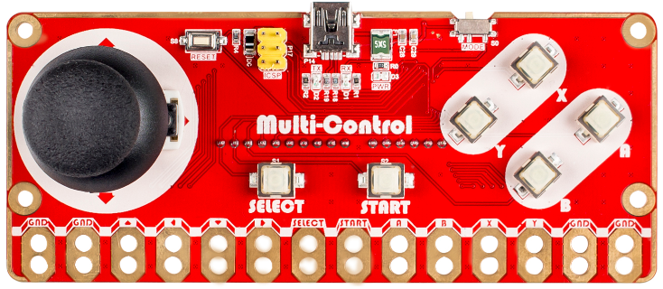
The front view is as follows:
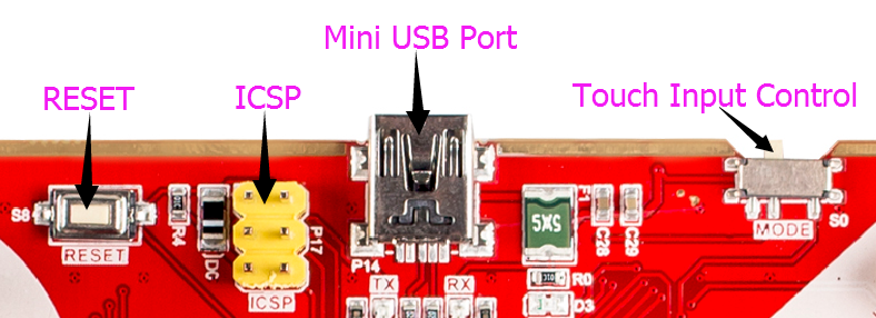
A reset switch, an ICSP 6-pin header, a Mini USB port and a touch input control. Touch input control switch is to turn the touch input on/off, to avoid unintended touch. ICSP 6-pin header is to write bootload to the chip and a mini USB port to upload the control program.
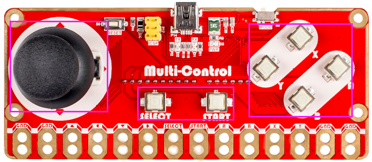
There are 6 silica gel buttons and a joystick.
Besides the buttons, there are 4 GND ports and another 10 analog touch input ports.
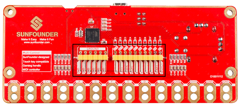
On the back of the board, there are 2 groups of pin headers including one group of GND, and the other corresponding to the input of the 10 keys. They are reserved for extending more control functions.
Check carefully, you can see the pin definition on touch input and pin headers are the same with buttons and the joystick, meaning they can realize the same functions. For example, we can connect the pins of Up, Down, Left, and Right of the touch input or pin headers to realize the same control of the 4 directions by the joystick.
Functions
The SunFounder Multi-Control can simulate the gamepad, MIDI input device, and PC keyboard.
Gamepad Mode
The operation is the same as using a general gamepad and quite suitable for the Retropie games.
Both the buttons & joystick and touch input & pin header can be applied in this mode.
MIDI Mode
Only touch input can be used in this mode. You can check mark on each touch input of tones on the back of Multi-control board.
It is used with alligator clip cables. One clip at a cable end bites the GND hole on the board and one at the other to the user. More clips connect the holes to conductors and the user inputs midi signals by touching the conductor (s). The operation and principle are quite similar with the FruitKey developed by SunFounder.
Keyboard Mode
In this mode, we make Multi-control a keyboard, which can realize the same functions.
Both the joystick and buttons and the touch input and pin headers can be applied in this mode.
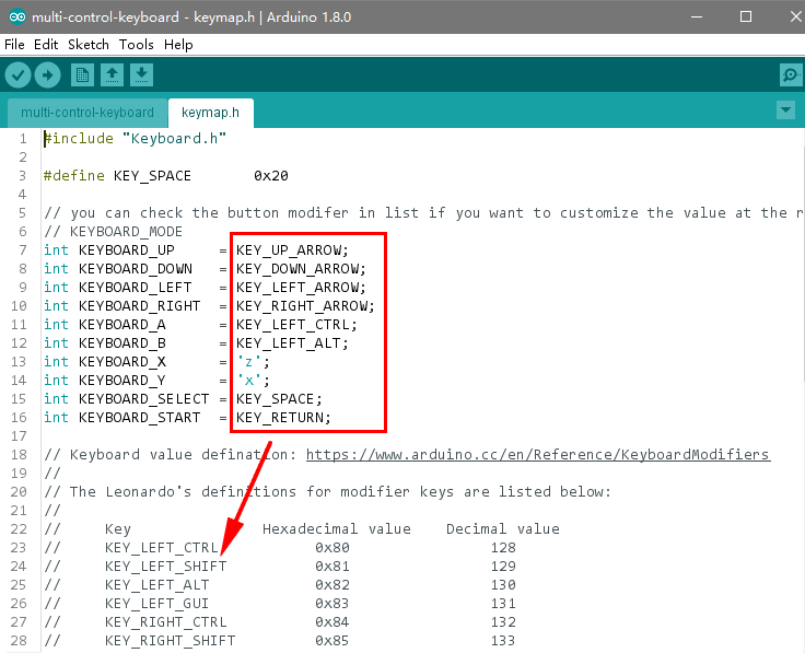
Multi-control equals to a keyboard with 10 keys. You can self-define the key mapping by modifying the key value in the header file (later we will show you how). By default, A is mapped to the left Ctrl, B to left Alt, X to Z, Y to X, SELECT to Space, and START to Enter. The joystick acts the same as the up, down, left, and right arrow keys on the keyboard.
Features
1.Small size: 120 x 50 x 32 mm
2.Fixing Hole: M3, sizing 113mm (H) x 31mm (V)
3.Communication with the master via mini USB
4.Supply Voltage: 5V (powered by USB)
5.With 6 buttons, 1 joystick, 10 touch contacts, 10 pin headers (6 share the same IO ports with the buttons)
6.Contains 1 ICSP pin header, 1 Reset switch, and 1 Mode toggle switch.
Test
Add Library
Before uploading the code, we need to download and add two libraries joystick and MIDIUSB first.
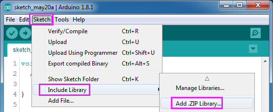
Open Arduino IDE, select Sketch->Include Library->Add .ZIP Library
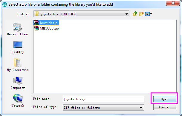
Select joystick.zip, and click Open.
Then Include MIDIUSB library in the same way.
Upload the Code
There are three Arduino code folders in the code package download-SunFounder_Multi_Control, including joystick, keyboard, and midi. When you upload a program to the Multi-Control, it can realize the specific function.
Here we take joystick as an example. Take the following procedures.
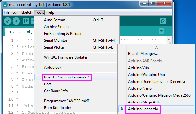
Choose the board: Tools ->Board->Arduino Leonardo.
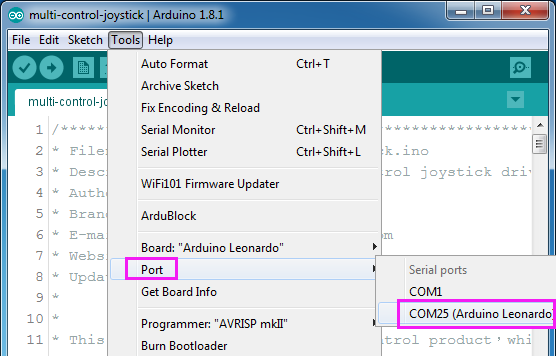
Then select Tools ->Port and select the port you just checked on Device Manager.
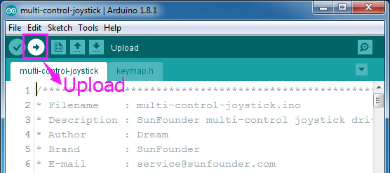
Click the Upload icon to upload the sketch to your board.
Wait till it’s done.
Check the Device
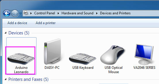
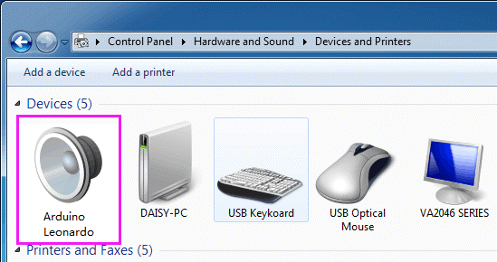
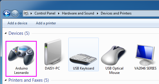
After the code is uploaded, check whether the device is recognized by the computer. Click Control Panel -> Hardware and Sound -> Device and Printers. Different devices will be recognized for uploading different code.
For instance, if you upload multi-control-keyboard, it will be recognized as a Keyboard.
If you upload multi-control-midi, it will be recognized as an Arduino Leonardo device.
If you upload multi-control-joystick, it will be recognized as a gamepad.
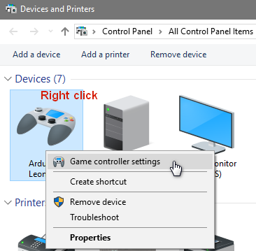
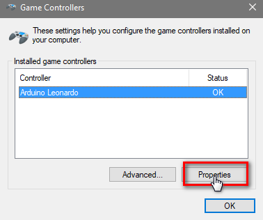
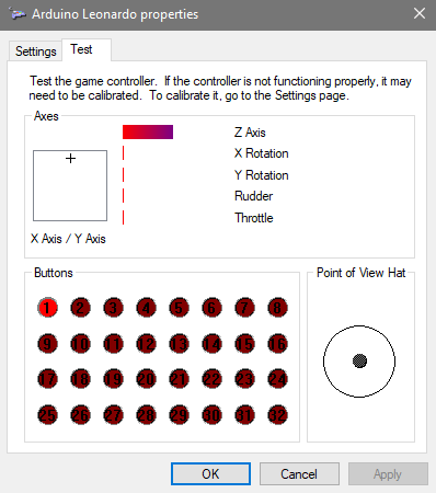
Here we can configure the gamepad: right click on it, on the pop-up menu click Game controller settings -> Properties. Then push the stick or press any key to see the test result.
Gamepad Mode
Preparations
In Gamepad Mode, a Raspberry Pi will be used with the Multi-Control to make a gamepad for RetroPie games. Besides an SD card for Raspberry Pi and a power adapter, you still need to prepare the following accessories:
1 x Multi-Control
1 x Mini USB Cable
1 x Raspberry Pi
1 x HDMI display with a cable
Procedures
1. Upload the code multi-control-gamepad to the Multi-Control
2. Download and install the image of RetropPie to the SD card. For more details, please click: https://retropie.org.uk/docs/First-Installation/
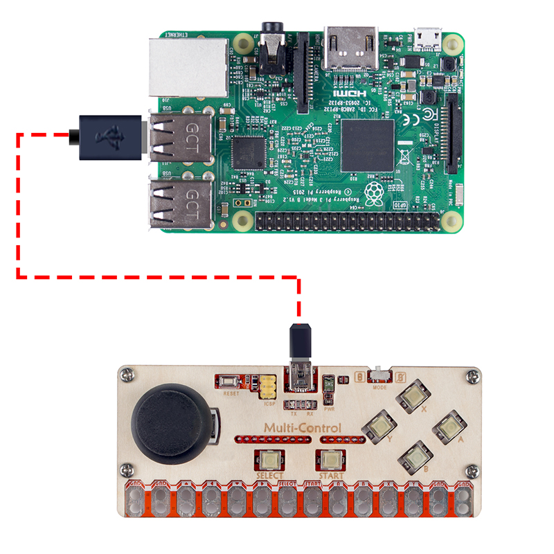
3. Connect the Raspberry Pi to Multi-Control with the Mini USB cable, power the RPi and the display, and then you can start playing games!
4. You can also use touch input or pin headers on the board’s back to make it
Keyboard
In the keyboard mode:
You can play many games by using just a few buttons, Multi-Control with key mapping is enough for it. Similarly, upload the code of keyboard to multi-control. Then connect it to the computer via USB and it can then be used as a keyboard for simple games.
Modify the Key Mapping of the Board
To change the key mapping of the Multi-Control, you can modify the header file keymap.h in the keyboard folder.
Midi
Use the alligator clip cables to make a midi device. One clip at a cable end bites the GND hole on the board and one at the other to the user. More clips connect the holes to conductors and the user inputs midi signals by touching the conductor (s).
A midi player is needed here, and a software named VMPK for computers and mobile devices is recommended here. You can also use other similar midi player apps.
Change the Instruments under Midi
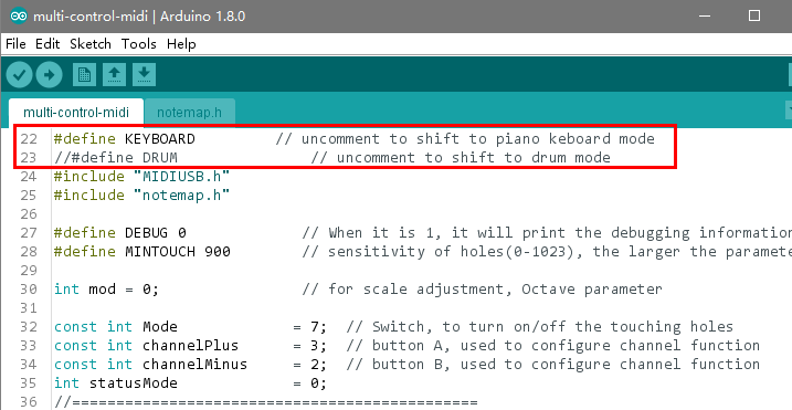
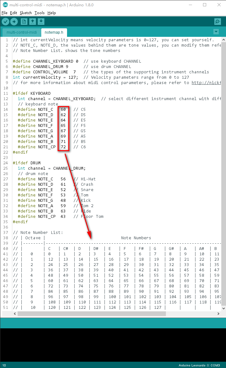
You can change the instruments that midi simulates by modifying the midi.ino file.
