Difference between revisions of "Joystick PS2 Module"
(→Introduction) |
(→Joystick PS2 in the experiment--Procedures) |
||
| Line 18: | Line 18: | ||
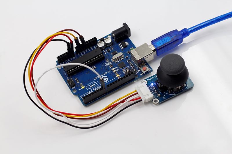
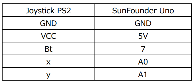
The wiring between the Joystick PS2 and SunFounder Uno board:<br> | The wiring between the Joystick PS2 and SunFounder Uno board:<br> | ||
[[File:Joystick3.png]] | [[File:Joystick3.png]] | ||
| − | [[File:Joystick4.png]] | + | [[File:Joystick4.png]]<br> |
Step 2: Program<br> | Step 2: Program<br> | ||
Step 3: Compile <br> | Step 3: Compile <br> | ||
Revision as of 08:18, 23 March 2016
Contents
Introduction
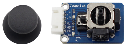
The joystick PS2 module two lines of analog output (X, Y) and one of digital output (Z). The cross rocker is a bidirectional 10k resistor; its resistance changes with different directions. Push the joystick towards different directions and the voltage read increases or decreases; press it down, then the output is low level and the corresponding LED lights up; otherwise it stays off.
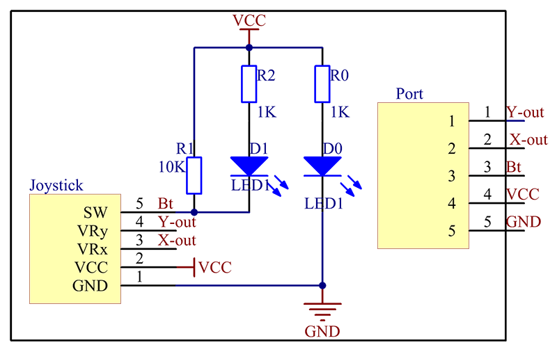
The schematic diagram of the module is as follows:
Application
The module can be applied to convenient control of objects (like a two-degree of freedom servo mount) to move in a two-dimensional space. It can be used in the remote controller for many robot projects
Joystick PS2 in the experiment--Components
- 1 * SunFounder Uno board
- 1 * USB data cable
- 1 * Joystick PS2 module
- 1 * 5-Pin anti-reverse cable
Joystick PS2 in the experiment--Procedures
Step 1: Build the circuit
The wiring between the Joystick PS2 and SunFounder Uno board:
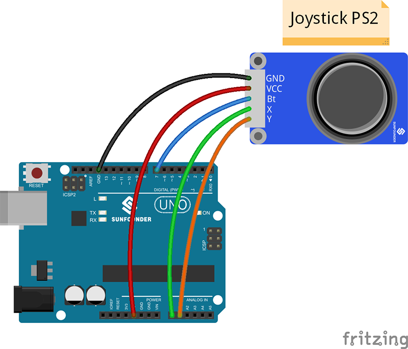
Step 2: Program
Step 3: Compile
Step 4: Upload the sketch to SunFounder Uno board
Now, push the rocker and the coordinates of X and Y axes displayed on Serial Monitor will change accordingly; press the button, and the coordinate of Z=0 will also be displayed.
