Difference between revisions of "Full Color RGB LED Matrix Driver Shield + RGB Matrix Screen"
(→Code) |
(→Resources) |
||
| (17 intermediate revisions by the same user not shown) | |||
| Line 1: | Line 1: | ||
=='''Introduction'''== | =='''Introduction'''== | ||
| + | <br> | ||
[[File:Fvdvd.png]]<br> | [[File:Fvdvd.png]]<br> | ||
| − | This is a full-color RGB LED matrix driver shield. It functions just like the Colorduino, though simplified, except that it does not support cascading. The code of the two is completely compatible. Just plug the module onto a Uno board (Arduino, SunFounder, or other compatibles) for use. DM163 is used as the driver chip on the driver shield. <br> | + | <br> |
| + | This is a [https://www.sunfounder.com/full-color-rgb-led-matrix-driver-shield-rgb-matrix-screen.html full-color RGB LED matrix driver shield]. It functions just like the Colorduino, though simplified, except that it does not support cascading. The code of the two is completely compatible. Just plug the module onto a Uno board (Arduino, SunFounder, or other compatibles) for use. DM163 is used as the driver chip on the driver shield. <br> | ||
You can just plug the 8x8 RGB LED dot matrix screen on the shield for use. It supports display of all the three primary colors, namely, red, green and blue, either separately or in a mixed way, and can flash at most 256 x 256 x 256 = 16,777,216 colors display. <br> | You can just plug the 8x8 RGB LED dot matrix screen on the shield for use. It supports display of all the three primary colors, namely, red, green and blue, either separately or in a mixed way, and can flash at most 256 x 256 x 256 = 16,777,216 colors display. <br> | ||
Working current: ≤300mA; operating temperature range: -10℃ ~ +50℃<br> | Working current: ≤300mA; operating temperature range: -10℃ ~ +50℃<br> | ||
Working voltage: 5V DC; PCB size: 6.0 x 6.0 cm<br> | Working voltage: 5V DC; PCB size: 6.0 x 6.0 cm<br> | ||
| + | |||
=='''Schematic'''== | =='''Schematic'''== | ||
| − | [http:// | + | [http://wiki.sunfounder.cc/images/8/8c/RGBmatrix_V2.PDF RGBmatrix Schematic][[File:PDF.jpg]]<br> |
In schematic, B[0,7] and R[0,7] control pin 1-16 of the RGB Matrix, when P[0,7] and G[0,7] do pin 16-32. DM163 is an 8x3-channel constant current LED driver chip, which controls pins of an 8x3 RGB Matrix. The Common-anode pins (P[0,7]) of the matrix RGB Matrix is controlled by the M54564P chip. <br> | In schematic, B[0,7] and R[0,7] control pin 1-16 of the RGB Matrix, when P[0,7] and G[0,7] do pin 16-32. DM163 is an 8x3-channel constant current LED driver chip, which controls pins of an 8x3 RGB Matrix. The Common-anode pins (P[0,7]) of the matrix RGB Matrix is controlled by the M54564P chip. <br> | ||
| Line 14: | Line 17: | ||
=='''Application'''== | =='''Application'''== | ||
When you get the RGB LED Matrix Driver Shield, first check that the RGB Matrix is plugged in the correct way (namely orientation). Just remove the matrix from the shield (or skip it, if you're sure the pin 1 of the two boards is connected). On the back pin 1 is marked, so plug that pin to pin 1 of the shield, as shown below. <br> | When you get the RGB LED Matrix Driver Shield, first check that the RGB Matrix is plugged in the correct way (namely orientation). Just remove the matrix from the shield (or skip it, if you're sure the pin 1 of the two boards is connected). On the back pin 1 is marked, so plug that pin to pin 1 of the shield, as shown below. <br> | ||
| + | <br> | ||
[[File:Gsdgfd.png]]<br> | [[File:Gsdgfd.png]]<br> | ||
| + | <br> | ||
Then plug the RGB LED Matrix Driver Shield to the UNO board. Also pay attention to the pins. See the figure below for direction.<br> | Then plug the RGB LED Matrix Driver Shield to the UNO board. Also pay attention to the pins. See the figure below for direction.<br> | ||
| − | [[File: | + | <br> |
| + | [[File:RGBMATRIX1.jpg]]<br> | ||
| + | <br> | ||
| + | |||
=='''Code'''== | =='''Code'''== | ||
Download the package '''RGBMatrix_library.zip'''. Save it to the folder libraries in Arduino (if you cannot find the path in Arduino, open Arduino IDE, select '''Sketch''' -> '''Include Library''' ->'''Add .ZIP Library'''…, find the file '''RGBMatrix.zip''' and click Open. So the RGBMatrix_library is added.<br> | Download the package '''RGBMatrix_library.zip'''. Save it to the folder libraries in Arduino (if you cannot find the path in Arduino, open Arduino IDE, select '''Sketch''' -> '''Include Library''' ->'''Add .ZIP Library'''…, find the file '''RGBMatrix.zip''' and click Open. So the RGBMatrix_library is added.<br> | ||
| − | [[File:Fdsfds.png]] | + | <br> |
| + | [[File:Fdsfds.png]]<br> | ||
| + | <br> | ||
Now go to the path \RGBMatrix_library\examples\RGBMatrix\ and open the file RGBMatrix.ino. In the IDE, select the right board and port, click '''Upload'''. Then you can see the RGB Matrix show letters A-Z in upper case, in lower case,and numbers, characters, etc. <br> | Now go to the path \RGBMatrix_library\examples\RGBMatrix\ and open the file RGBMatrix.ino. In the IDE, select the right board and port, click '''Upload'''. Then you can see the RGB Matrix show letters A-Z in upper case, in lower case,and numbers, characters, etc. <br> | ||
| + | <br> | ||
[[File:Vxcv.png]]<br> | [[File:Vxcv.png]]<br> | ||
| − | + | <br> | |
| − | [http:// | + | You can also upload the [https://github.com/frederickk/Colorduino Colorduino]code RGB LED Matrix Driver Shield. It enables flowing color changes. <br> |
| + | [http://wiki.sunfounder.cc/index.php?title=RGB_Dot_Matrix_Explanation RGB_Dot_Matrix_Explanation]This document is the explanation for RGB Matrix. Hope it can help you better understand its structure and using. | ||
=='''Resources'''== | =='''Resources'''== | ||
| − | [http:// | + | [http://wiki.sunfounder.cc/images/4/44/DM163_datasheet.pdf DM163_datasheet][[File:PDF.jpg]]<br> |
| − | [http:// | + | [http://wiki.sunfounder.cc/images/6/66/M54564P_datasheet.pdf M54564P_datasheet][[File:PDF.jpg]]<br> |
| − | [http:// | + | [http://wiki.sunfounder.cc/images/1/11/RGBMatrix_library.zip RGBMatrix_library][[File:ZIP.jpg]] |
Latest revision as of 07:14, 20 March 2017
Introduction
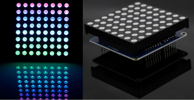
This is a full-color RGB LED matrix driver shield. It functions just like the Colorduino, though simplified, except that it does not support cascading. The code of the two is completely compatible. Just plug the module onto a Uno board (Arduino, SunFounder, or other compatibles) for use. DM163 is used as the driver chip on the driver shield.
You can just plug the 8x8 RGB LED dot matrix screen on the shield for use. It supports display of all the three primary colors, namely, red, green and blue, either separately or in a mixed way, and can flash at most 256 x 256 x 256 = 16,777,216 colors display.
Working current: ≤300mA; operating temperature range: -10℃ ~ +50℃
Working voltage: 5V DC; PCB size: 6.0 x 6.0 cm
Schematic
In schematic, B[0,7] and R[0,7] control pin 1-16 of the RGB Matrix, when P[0,7] and G[0,7] do pin 16-32. DM163 is an 8x3-channel constant current LED driver chip, which controls pins of an 8x3 RGB Matrix. The Common-anode pins (P[0,7]) of the matrix RGB Matrix is controlled by the M54564P chip.
The Arduino board controls the M5456HP by 8 digital I/Os, while DM163 communicates with the board via the I2C bus.
Application
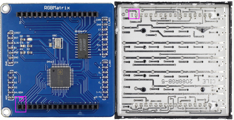
When you get the RGB LED Matrix Driver Shield, first check that the RGB Matrix is plugged in the correct way (namely orientation). Just remove the matrix from the shield (or skip it, if you're sure the pin 1 of the two boards is connected). On the back pin 1 is marked, so plug that pin to pin 1 of the shield, as shown below.
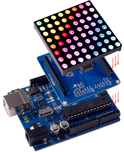
Then plug the RGB LED Matrix Driver Shield to the UNO board. Also pay attention to the pins. See the figure below for direction.
Code
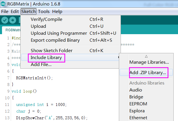
Download the package RGBMatrix_library.zip. Save it to the folder libraries in Arduino (if you cannot find the path in Arduino, open Arduino IDE, select Sketch -> Include Library ->Add .ZIP Library…, find the file RGBMatrix.zip and click Open. So the RGBMatrix_library is added.
Now go to the path \RGBMatrix_library\examples\RGBMatrix\ and open the file RGBMatrix.ino. In the IDE, select the right board and port, click Upload. Then you can see the RGB Matrix show letters A-Z in upper case, in lower case,and numbers, characters, etc.
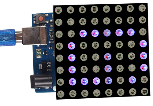
You can also upload the Colorduinocode RGB LED Matrix Driver Shield. It enables flowing color changes.
RGB_Dot_Matrix_ExplanationThis document is the explanation for RGB Matrix. Hope it can help you better understand its structure and using.