Esp8266 Wifi Module
Contents
Preparation
-1 * PL2303HXD
-1 * SunFounder Uno Board
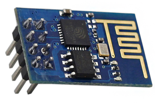
-1 * ESP8266
Procedures
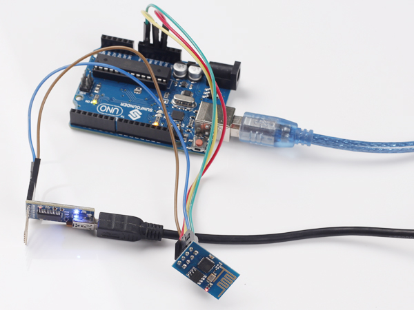
Step 1: wire
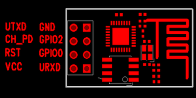
Connect UTXD of ESP8266 to RXD of PL2303, URXD to TXD, CH_PD to 5v, GND to GND, and VCC to 3.3v. The Uno board here is used to supply 3.3v power. PL2303 is a USB to Serial Bridge Controller. You can also use other components, such as FTDI.
Step 2:set parameters
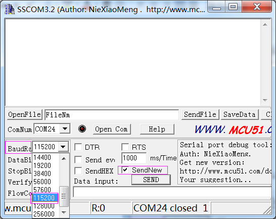
After wiring, open the serial port debug tool sscom32. Set parameters at first.
1) Open the serial port, click Open Com. Select the correct port, as shown below.
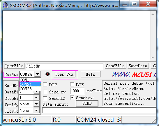
2) Select the correct baud rate. Here select 115200 bps. Click SendNew, as shown below.
Step3:AT instructions
Now, you can start to send instructions. Enter "AT+RST" in the text box. It’s used to restart the module. If ESP8266 goes well, OK will be sent, as shown below:
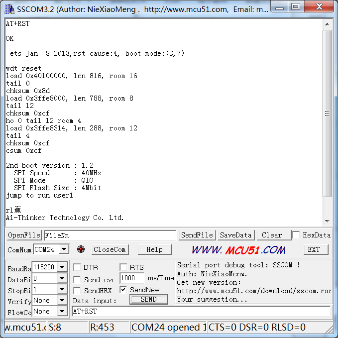
You can also send other instructions, such as "AT+GMR". It is used to check the version of AT commands and SDK that you are using, the type of which is "executed".
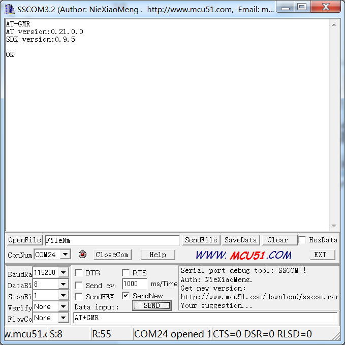
For more information about ESP8266 AT Instructions. please refer to 4A-ESP8266__AT Instrction Set__EN_v0.23.pdf.
Resource
ESP8266_AT_Instrction_Set
ESP8266_Module_User_Guide
ESP8266_Datasheet
Sscom32E
