ADXL345 3-Axis Digital Acceleration of Gravity Tilt Module (GY-291)
Contents
[hide]Introduction
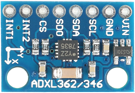
ADXL345 is a low-power consumption triaxial accelerometer with tiny and thin appearance. It can measure the acceleration that reaches ±16 g with high resolution (13 bits). The output data mode of ADXL345 is 16-bit binary complement that you can access through SPI (line 3 or line 4) or I2C digital interface.
Application
- Mobile Phone
- Medical instrument
- Game and pointing device
- Industrial instrument
- Personal navigation device
- HDD Protection from falling
- Screen flip on tablet computer
Main Features
- Type: GY-291
- Chip: ADXL345
- Power Supply: 3~5V
- Communication Mode: Standard IIC/SPI communicating protocol
- Measuring Range: ±2g±16g
- 3 axis, ± 2g/ ± 4g/ ± 8g/ ± 16g
Introduction of Pins
| Introduction of Pins | |
|---|---|
| GND | Cathode of the power supply. |
| VCC | Anode of the power supply is connected to 3-5V. |
| CS | Chip select. |
| INT1 | Interrupt the output 1. |
| INT2 | Interrupt the output 2. |
| SD0 | Serial data output (SPI 4 wire), spare I2C address choose(I2C). |
| SDA | Serial data (I2C), Serial data input (SPI line 4), Serial data input, output(SPI Line 3) |
| SCL | Serial data (I2C), Serial data input (SPI line 4), Serial data input, output(SPI Line 3) |
Principle
ADXL346 is a complete 3-axis acceleration measurement system. Its selectable measurement ranges can be ±2 g, ±4 g, ±8 g or ±16 g. The component can not only measure the dynamic acceleration cased by movement or shock, but the static acceleration, such as gravity acceleration; so it can work as a tilt sensor.
The sensor applies micromachining structure of polycrystal surface and puts it on the top of the wafer. The polycrystal spring hangs over the surface structure of the wafer and supplies the resistance cased by the acceleration.
The independent fixed board of the differential capacitance is combined with the active mass connection board and it can measure the deviation of the structure. Acceleration gives the mass detection block a deflection and lets the differential capacitance be out-of-balance. So the output range of the sensor is in proportion to the acceleration. Phase sensitive demodulation uses and ascertains the range and polarity of acceleration.
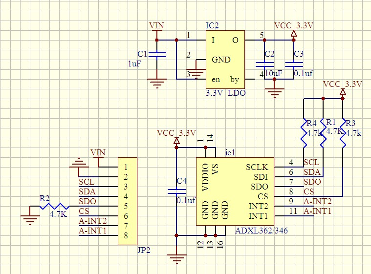
Experimental Procedures for Arduino
Step 1: Connect the circuit:
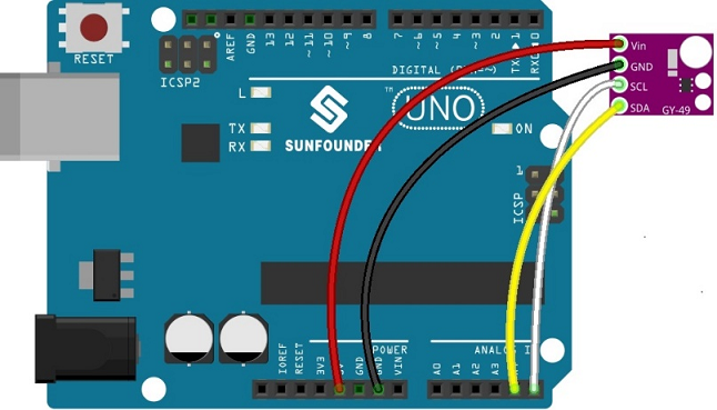
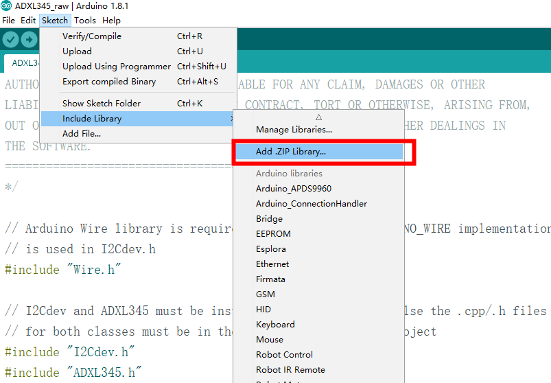
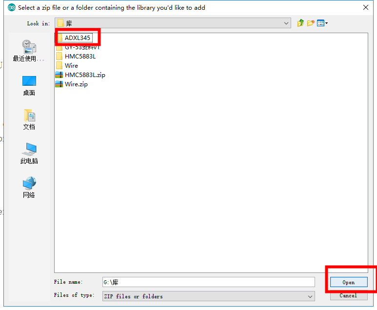
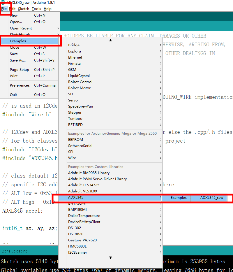
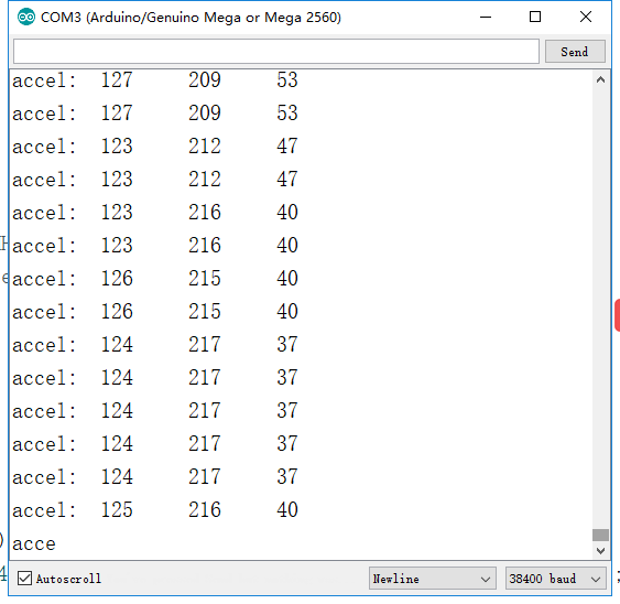
Step 2: Compile and upload the code.
