Difference between revisions of "10.1 Inch HDMI IPS LCD Monitor Operating Instructions"
(→Features) |
(→Method A (highly recommended)) |
||
| (26 intermediate revisions by the same user not shown) | |||
| Line 1: | Line 1: | ||
| − | |||
==Introduction== | ==Introduction== | ||
| − | [[File: | + | [[File:IPS LCD1.jpg]]<br> |
| − | + | The 10.1 Inch HDMI Monitor is packaged with a power adapter and HDMI cable. It adopts the IPS display and can be applied to Raspberry Pi. <br> | |
==Features== | ==Features== | ||
| − | + | Screen: 10.1 Inch IPS LCD Screen<br> | |
| − | + | Resolution: 1280*800 (16:10)<br> | |
| − | + | Input Signal: VGA, AV, HDMI<br> | |
| − | Power: DC12V | + | Power: DC12V<br> |
| − | Consumption: | + | Consumption: 10W<br> |
| − | + | Operate mode: Key operation <br> | |
| − | + | [[File:IPS LCD2.jpg]]<br> | |
| − | [[File: | + | [[File:IPS LCD3.jpg]]<br> |
| + | |||
| + | ==Control== | ||
| + | ===Monitor Keys=== | ||
| + | [[File:IPS LCD4.jpg]] | ||
| + | {| border="1" class="wikitable" | ||
| + | |- | ||
| + | ! scope="col" |Key | ||
| + | ! scope="col" |On Monitor | ||
| + | ! scope="col" |Under MENU | ||
| + | |- | ||
| + | |align="center"|POWER | ||
| + | |align="center"|ON/OFF | ||
| + | |align="center"|ON/OFF | ||
| + | |- | ||
| + | |align="center"|MENU | ||
| + | |align="center"|Open the menu | ||
| + | |align="center"|Confirm | ||
| + | |- | ||
| + | |align="center"|INCREASE | ||
| + | |align="center"|Volume | ||
| + | |align="center"|Down/Increase | ||
| + | |- | ||
| + | |align="center"|DECREASE | ||
| + | |align="center"|Color Mode | ||
| + | |align="center"|Up/Decrease | ||
| + | |- | ||
| + | |align="center"|MODE SELECT | ||
| + | |align="center"|Select a mode | ||
| + | |align="center"|Return | ||
| + | |} | ||
| + | |||
| + | Note: Under MENU, there are mufunctions: Color, Adjust, OSD, Function, Sound and Exit. And under MODE SELECT, you can select AV1, AV2 (the jack is set inside so unavailable), VGA, and HDMI. <br> | ||
| − | == | + | ==Raspberry Pi Installation== |
| − | + | ||
| − | + | ||
| − | + | You'll see 4 sets of acrylic plates in the package, as shown in the left figure below. The three bigger ones are to protect the Raspberry Pi (suitable for model B+, 2 model B and 3 model B), and the much smaller one is an SD card removing assistant.<br> | |
| − | + | To protect the plates, sticker is added to both sides. To unveil the real face of the acrylics, you need to remove these "masks". Raise the edge of the stick on a plate, preferably with your finger nail because a knife may scratch the acrylic and leave a scar. Then pull the sticker – be careful when pulling since the acrylic may be very vulnerable and easy to break, especially the middle thinner part of the white transparent set. <br> | |
| − | + | [[File:IPS LCD5.jpg]]<br> | |
| − | + | [[File:IPS LCD6.jpg]]<br> | |
| − | + | After removing all the stickers, you can see the colorful acrylics then!<br> | |
| − | + | [[File:IPS LCD7.jpg]]<br> | |
| − | + | Next, turn the monitor upside down, unscrew the 4 copper standoffs on the back. Note that you should just take out the four ones at the top, and leave the rest 4 ones unmoved. If you've loosened the latter, remember to tighten them. <br> | |
| − | [[File: | + | |
| − | + | ||
| − | + | [[File:IPS LCD8.jpg]]<br> | |
| − | + | ||
| − | + | After removing the 4 standoffs on top, make sure the 4 ones at bottom are tightened, and then place the blue acrylic onside. Pay attention to the direction: place the acrylic with the opening at your right side (the buttons side, see the red arrow below) for the SD card. Also the long slot should be placed at the top of the monitor which is to leave the room for pin tips underneath the board (green arrow). So now put the Raspberry Pi on the acrylic. You're suggested to plug in the SD card before fixing, or else it will be tricky to do so after installation is done. Accordingly, note that pins at the monitor top and SD card at the buttons side.<br> | |
| − | + | [[File:IPS LCD9.jpg]]<br> | |
| − | + | ||
| − | + | ||
| − | + | [[File:IPS LCD10.jpg]]<br> | |
| − | + | ||
| − | + | ||
| − | |||
| − | |||
| − | |||
| − | |||
| − | |||
| − | + | Then cover the transparent acrylic plate. As aforementioned, the middle parts are thin and fragile, so when placing, BE GENTLE! Otherwise they may be broken. After that, place the yellow-green acrylic onside and screw back the 4 copper standoffs. <br> | |
| − | + | ||
| − | + | ||
| − | + | ||
| − | + | [[File:IPS LCD11.jpg]]<br> | |
| − | + | [[File:IPS LCD12.jpg]]<br> | |
| − | + | ||
| − | + | ||
| − | [[File: | + | |
| + | At this time, if you cannot screw the nut back because the screw is "too short", it indicates that you've assembled the acrylics wrong which results in a higher prop height than supposed. Check whether they are done correctly based on the steps above. <br> | ||
| + | So now the assembly is done! You should notice the small hook-shape acrylic, which is to remove the SD card and also can be used to hook the FFC connector of CSI/DSI.<br> | ||
| − | + | [[File:IPS LCD13.jpg]]<br> | |
| − | [[File: | + | |
| + | [[File:IPS LCD14.jpg]]<br> | ||
| − | + | [[File:IPS LCD15.jpg]]<br> | |
| − | + | ||
| − | [[File: | + | So it's all done! <br> |
| − | + | ||
| + | [[File:IPS LCD16.jpg]]<br> | ||
| − | + | <span style="color:red">Before any operations, please read the following instructions carefully.</span><br> | |
| − | + | ||
| + | ==Instructions on Monitor Settings for Raspberry Pi== | ||
| + | Step 1: Connect Raspberry Pi <br> | ||
| + | Plug the TF memory card with the Raspbian system burnt into the Raspberry Pi. Then connect the display and the power of the Raspberry Pi.<br> | ||
| − | + | Step 2: Select HDMI mode<br> | |
| − | + | After boot up, if the screen shows no signal and turn black, press the bottom MODE SELECT button and select the HDMI mode. The screen will then display the homepage. <br> | |
| + | During the use, if you have problems about resolution and sound, check the following guide.<br> | ||
| + | ===- Issue 1: Wrong Resolution === | ||
| + | If you encounter the difficulties in reading too small characters or incomplete display, that would be wrong resolution. Here let's see how to solve this resolution issue. <br> | ||
| − | === | + | ====- Solution==== |
| − | + | To solve issue, here we should adjust the screen display and modify the /boot/config.txt file. Take the following procedures. <br> | |
| − | + | Step 1: Open config.txt<br> | |
| + | You need to edit the config.txt file to adjust the solution. There are two methods to open it for editing. <br> | ||
| + | ====Method A (highly recommended)==== | ||
| + | First, you need a USB mouse and a USB keyboard connected to your Raspberry Pi. After your Raspberry Pi is booted up, it should display a GUI as follows:<br> | ||
| − | |||
| − | |||
| − | |||
| + | [[File:IPS LCD17.png]]<br> | ||
| − | |||
| − | |||
| + | Click on the black icon, which represents terminal, on the top left: <br> | ||
| − | + | [[File:IPS LCD18.png]]<br> | |
| − | [[File: | + | |
| + | A terminal now pops up. Then type in commands: <br> | ||
| + | sudo leafpad /boot/config.txt | ||
| + | Press Enter to confirm<br> | ||
| + | A window of leafpad editor shows up:<br> | ||
| − | + | [[File:IPS LCD19.png]]<br> | |
| − | [[File: | + | |
| + | |||
| + | Then move on to the next step for editing.<br> | ||
| + | If your Raspberry Pi is booted up to a CLI like this:<br> | ||
| − | + | [[File:IPS LCD20.png]]<br> | |
| − | [[File: | + | |
| − | + | Just type in: <br> | |
| − | + | sudo nano /boot/config.txt<br> | |
| + | And a nano editor will appear. Use your arrow keys on the keyboard to move the cursor, not by the mouse, and go to the next step for editing. Remember to save with Ctrl + O and exit the editor with Ctrl + X after you finish editing.<br> | ||
| + | |||
| + | ====Method B (not for NOOBS)==== | ||
| + | First prepare a computer running on Windows, Mac or Linux, and a TF card on which the Raspbian system has been burnt. Plug the TF card into the computer with a card reader.<br> | ||
| + | Now, open /boot and find the config.txt file. If your computer runs on Windows, DO NOT open the file by Microsoft Word (also better not to use Notepad) in case of format issues. You are advised to use other edit tools like Notepad++. <br> | ||
| + | ====Method C====<br> | ||
| + | Log in to Raspberry Pi remotely. <br> | ||
| + | Then run the command to edit config.txt<br> | ||
| + | sudo nano /boot/config.txt<br> | ||
| + | And a nano editor will appear. Use your arrow keys on the keyboard to move the cursor, not by the mouse, and go to the next step for editing. Remember to save with Ctrl + O and exit the editor with Ctrl + X after you finish editing.<br> | ||
| + | Step 2: Modify /boot/config.txt <br> | ||
| + | In either way, now the file config.txt is opened. <br> | ||
| + | 1) Define a custom CVT mode. Add the following lines below #hdmi_force_hotplug=1.<br> | ||
| + | hdmi_cvt=1024 600 60 3 0 0 0<br> | ||
| + | hdmi_cvt=<width> <height> <framerate> <aspect> <margins> <interlace> <rb><br> | ||
| + | |||
| + | {| border="1" class="wikitable" | ||
| + | |- | ||
| + | ! scope="col" | Value | ||
| + | ! scope="col" | Default | ||
| + | ! scope="col" | Description | ||
| + | |- | ||
| + | |align="center"|width | ||
| + | |align="center"|(required) | ||
| + | |align="center"|width in pixels | ||
| + | |- | ||
| + | |align="center"|height | ||
| + | |align="center"|(required) | ||
| + | |align="center"|height in pixels | ||
| + | |- | ||
| + | |align="center"|framerate | ||
| + | |align="center"|(required) | ||
| + | |align="center"|framerate in Hz | ||
| + | |- | ||
| + | |align="center"|aspect | ||
| + | |align="center"|3 | ||
| + | |align="center"|aspect ratio 1=4:3, 2=14:9, 3=16:9, 4=5:4, 5=16:10, 6=15:9 | ||
| + | |- | ||
| + | |align="center"|margins | ||
| + | |align="center"|0 | ||
| + | |align="center"|0=margins disabled, 1=margins enabled | ||
| + | |- | ||
| + | |align="center"|interlace | ||
| + | |align="center"|0 | ||
| + | |align="center"|0=progressive, 1=interlaced | ||
| + | |- | ||
| + | |align="center"|rb | ||
| + | |align="center"|0 | ||
| + | |align="center"|0=normal, 1=reduced blanking | ||
| + | |} | ||
| + | |||
| + | 2) Find the following lines (If there is a "#" mark at the beginning of any of the three lines, which means they are commented, delete the “#”mark to uncomment it). The asterisk "*" represents the value.<br> | ||
| + | hdmi_group=*<br> | ||
| + | hdmi_mode=*<br> | ||
| + | hdmi_drive=*<br> | ||
| + | 3) Modify the value, like this: <br> | ||
| + | hdmi_group=2<br> | ||
| + | hdmi_mode=87<br> | ||
| + | ....<br> | ||
| + | hdmi_drive=2<br> | ||
| + | hdmi_group=2 means DMT (Display Monitor Timings; the standard typically used by monitors)<br> | ||
| + | hdmi_mode=87 indicates the custom CVT mode as defined above. <br> | ||
| + | hdmi_drive=2 selects the Normal HDMI mode. <br> | ||
| + | For more details about configuring config.txt, refer to Raspberry Pi official website: go through HELP->DOCUMENTATION->CONFIGURATION->config.txt.<br> | ||
| + | After the modification is done, save and exit. <br> | ||
| + | 4) Reboot, or boot up the Raspberry Pi, you should see better display.<br> | ||
| + | |||
| + | ===- Issue 2: No Sound from the Monitor under Raspbian=== | ||
| + | ====- Solution==== | ||
| + | If the monitor makes no sound under Raspbian, you may try going to raspi-config -> Advanced Options and select Force HDMI.<br> | ||
| + | Click on the black icon, which represents terminal, on the top left: <br> | ||
| + | |||
| + | [[File:IPS LCD21.png]]<br> | ||
| + | |||
| + | |||
| + | A terminal now pops up. Run sudo raspi-config:<br> | ||
| + | |||
| + | [[File:IPS LCD22.png]]<br> | ||
| + | |||
| + | |||
| + | Select Advanced Options by pressing the up/down arrow key:<br> | ||
| + | |||
| + | [[File:IPS LCD23.png]]<br> | ||
| + | |||
| + | Press Enter.<br> | ||
| + | Next, on the pop-up window, select Audio in the same way: <br> | ||
| + | |||
| + | [[File:IPS LCD24.png]]<br> | ||
| + | |||
| + | Press Enter.<br> | ||
| + | |||
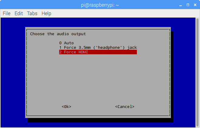
| + | On the window Choose the audio output, select Force HDMI: <br> | ||
| + | |||
| + | [[File:IPS LCD25.png]]<br> | ||
| + | |||
| + | Press Enter.<br> | ||
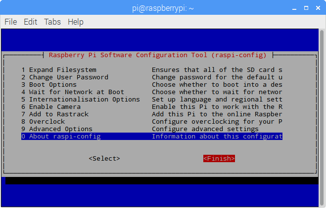
| + | Then return to the main menu and select Finish with the left/right key and press Enter to confirm and exit. <br> | ||
| + | |||
| + | [[File:IPS LCD26.png]]<br> | ||
| + | |||
| + | |||
| + | Now the speaker of the monitor should make sounds. Try to play a video on YouTube! <br> | ||
| + | Note: If it still make no sounds, you may need to raise the volume of the monitor and Raspberry Pi.<br> | ||
| − | == | + | ==Free Support== |
| − | + | If you have any TECHNICAL questions, add a topic under FORUM section on our website and we'll reply as soon as possible. <br> | |
| − | + | For NON-TECH questions like order and shipment issues, please send an email to service@sunfounder.com. You're also welcomed to share your projects on FORUM.<br> | |
| − | + | ||
| − | + | ||
| − | == | + | ==Copyright Notice== |
| − | + | All contents including but not limited to texts, images, and code in this manual are owned by the SunFounder Company. You should only use it for personal study, investigation, enjoyment, or other non-commercial or nonprofit purposes, under the related regulations and copyrights laws, without infringing the legal rights of the author and relevant right holders. For any individual or organization that uses these for commercial profit without permission, the Company reserves the right to take legal action.<br> | |
| − | + | ||
Latest revision as of 03:18, 3 November 2017
Contents
Introduction
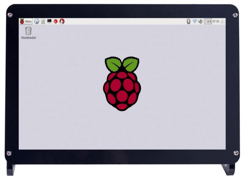
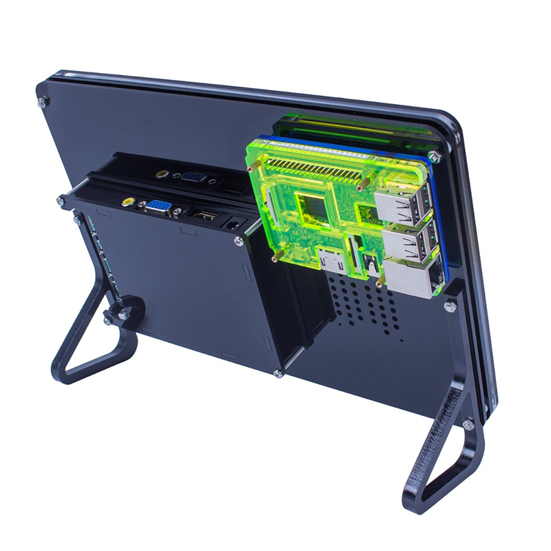
The 10.1 Inch HDMI Monitor is packaged with a power adapter and HDMI cable. It adopts the IPS display and can be applied to Raspberry Pi.
Features
Screen: 10.1 Inch IPS LCD Screen
Resolution: 1280*800 (16:10)
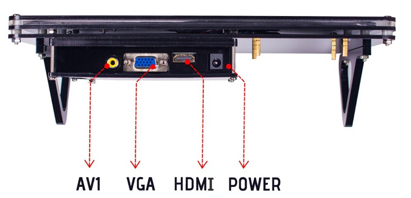
Input Signal: VGA, AV, HDMI
Power: DC12V
Consumption: 10W
Operate mode: Key operation
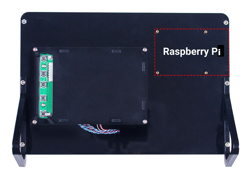
Control
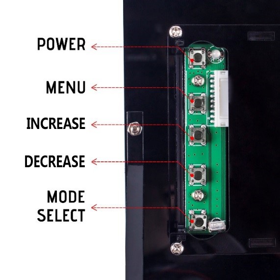
Monitor Keys
| Key | On Monitor | Under MENU |
|---|---|---|
| POWER | ON/OFF | ON/OFF |
| MENU | Open the menu | Confirm |
| INCREASE | Volume | Down/Increase |
| DECREASE | Color Mode | Up/Decrease |
| MODE SELECT | Select a mode | Return |
Note: Under MENU, there are mufunctions: Color, Adjust, OSD, Function, Sound and Exit. And under MODE SELECT, you can select AV1, AV2 (the jack is set inside so unavailable), VGA, and HDMI.
Raspberry Pi Installation
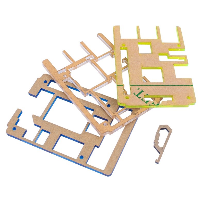
You'll see 4 sets of acrylic plates in the package, as shown in the left figure below. The three bigger ones are to protect the Raspberry Pi (suitable for model B+, 2 model B and 3 model B), and the much smaller one is an SD card removing assistant.
To protect the plates, sticker is added to both sides. To unveil the real face of the acrylics, you need to remove these "masks". Raise the edge of the stick on a plate, preferably with your finger nail because a knife may scratch the acrylic and leave a scar. Then pull the sticker – be careful when pulling since the acrylic may be very vulnerable and easy to break, especially the middle thinner part of the white transparent set.
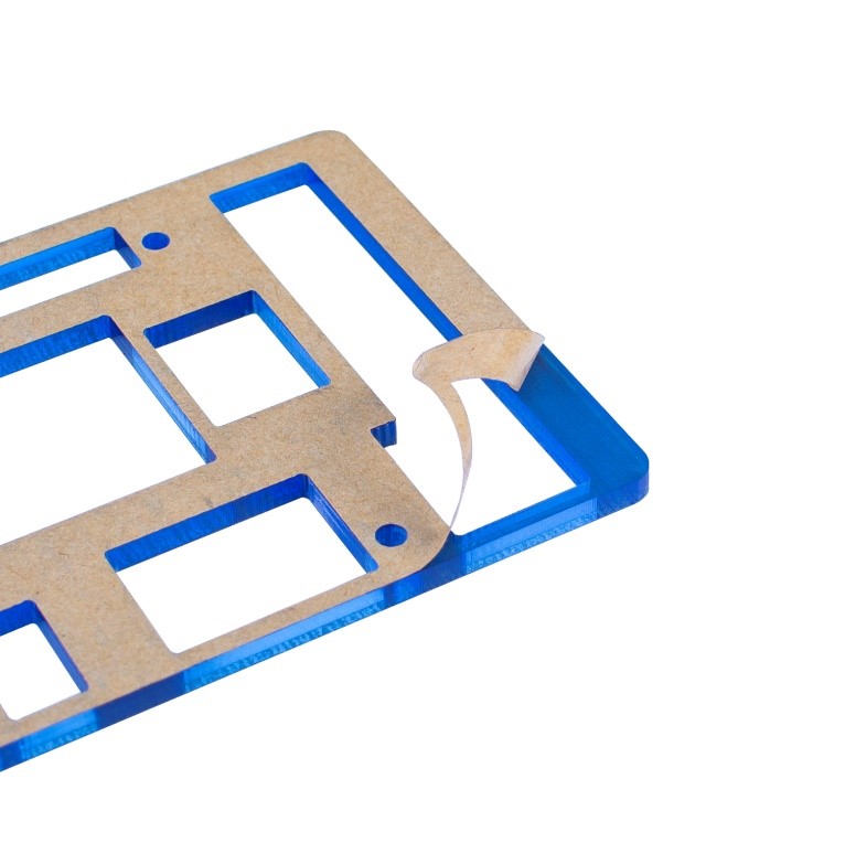
After removing all the stickers, you can see the colorful acrylics then!
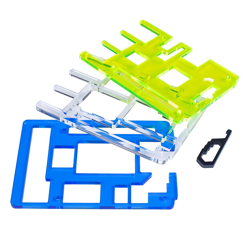
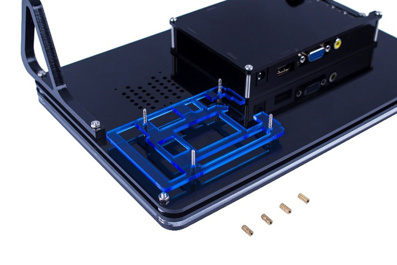
Next, turn the monitor upside down, unscrew the 4 copper standoffs on the back. Note that you should just take out the four ones at the top, and leave the rest 4 ones unmoved. If you've loosened the latter, remember to tighten them.
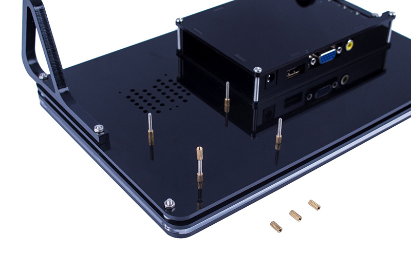
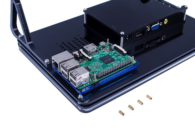
After removing the 4 standoffs on top, make sure the 4 ones at bottom are tightened, and then place the blue acrylic onside. Pay attention to the direction: place the acrylic with the opening at your right side (the buttons side, see the red arrow below) for the SD card. Also the long slot should be placed at the top of the monitor which is to leave the room for pin tips underneath the board (green arrow). So now put the Raspberry Pi on the acrylic. You're suggested to plug in the SD card before fixing, or else it will be tricky to do so after installation is done. Accordingly, note that pins at the monitor top and SD card at the buttons side.
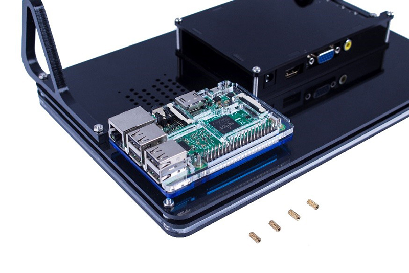
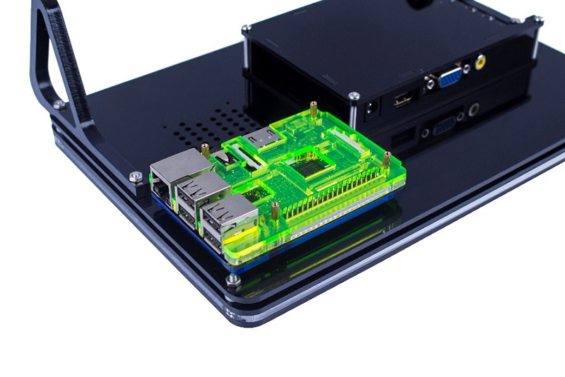
Then cover the transparent acrylic plate. As aforementioned, the middle parts are thin and fragile, so when placing, BE GENTLE! Otherwise they may be broken. After that, place the yellow-green acrylic onside and screw back the 4 copper standoffs.
At this time, if you cannot screw the nut back because the screw is "too short", it indicates that you've assembled the acrylics wrong which results in a higher prop height than supposed. Check whether they are done correctly based on the steps above.
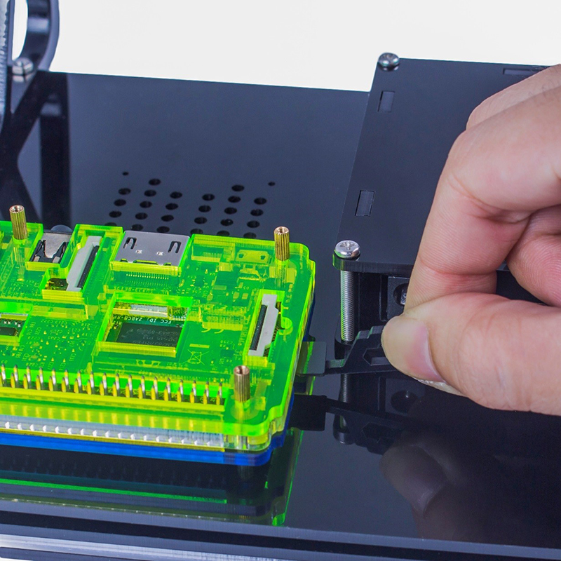
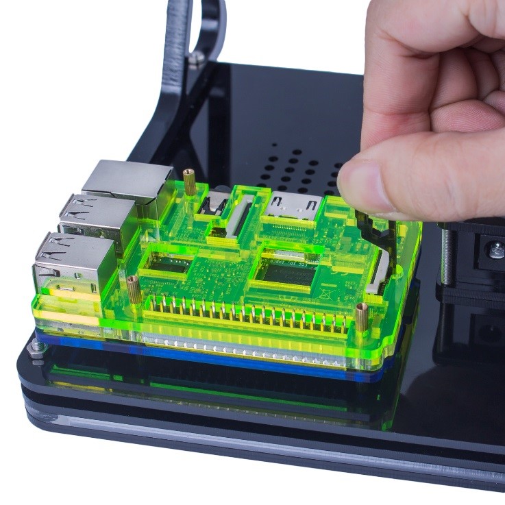
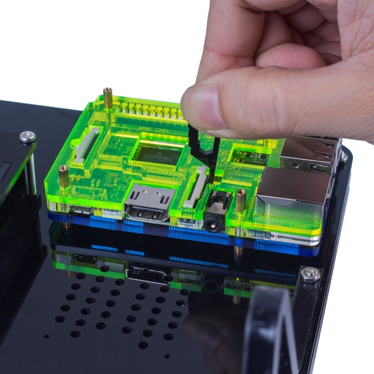
So now the assembly is done! You should notice the small hook-shape acrylic, which is to remove the SD card and also can be used to hook the FFC connector of CSI/DSI.
So it's all done!
Before any operations, please read the following instructions carefully.
Instructions on Monitor Settings for Raspberry Pi
Step 1: Connect Raspberry Pi
Plug the TF memory card with the Raspbian system burnt into the Raspberry Pi. Then connect the display and the power of the Raspberry Pi.
Step 2: Select HDMI mode
After boot up, if the screen shows no signal and turn black, press the bottom MODE SELECT button and select the HDMI mode. The screen will then display the homepage.
During the use, if you have problems about resolution and sound, check the following guide.
- Issue 1: Wrong Resolution
If you encounter the difficulties in reading too small characters or incomplete display, that would be wrong resolution. Here let's see how to solve this resolution issue.
- Solution
To solve issue, here we should adjust the screen display and modify the /boot/config.txt file. Take the following procedures.
Step 1: Open config.txt
You need to edit the config.txt file to adjust the solution. There are two methods to open it for editing.
Method A (highly recommended)
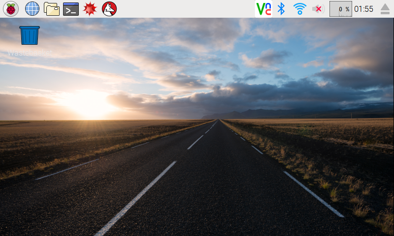
First, you need a USB mouse and a USB keyboard connected to your Raspberry Pi. After your Raspberry Pi is booted up, it should display a GUI as follows:
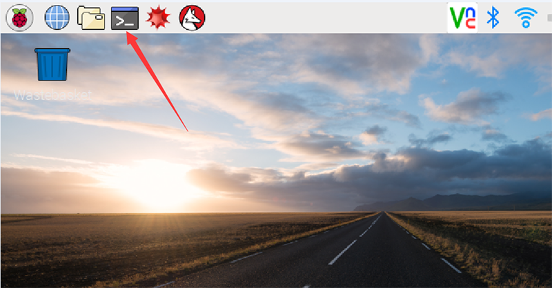
Click on the black icon, which represents terminal, on the top left:
A terminal now pops up. Then type in commands:
sudo leafpad /boot/config.txt
Press Enter to confirm
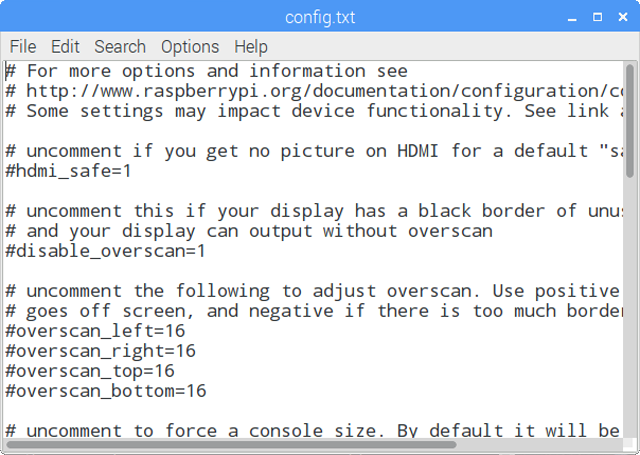
A window of leafpad editor shows up:
Then move on to the next step for editing.
If your Raspberry Pi is booted up to a CLI like this:
Just type in:
sudo nano /boot/config.txt
And a nano editor will appear. Use your arrow keys on the keyboard to move the cursor, not by the mouse, and go to the next step for editing. Remember to save with Ctrl + O and exit the editor with Ctrl + X after you finish editing.
Method B (not for NOOBS)
First prepare a computer running on Windows, Mac or Linux, and a TF card on which the Raspbian system has been burnt. Plug the TF card into the computer with a card reader.
Now, open /boot and find the config.txt file. If your computer runs on Windows, DO NOT open the file by Microsoft Word (also better not to use Notepad) in case of format issues. You are advised to use other edit tools like Notepad++.
====Method C====
Log in to Raspberry Pi remotely.
Then run the command to edit config.txt
sudo nano /boot/config.txt
And a nano editor will appear. Use your arrow keys on the keyboard to move the cursor, not by the mouse, and go to the next step for editing. Remember to save with Ctrl + O and exit the editor with Ctrl + X after you finish editing.
Step 2: Modify /boot/config.txt
In either way, now the file config.txt is opened.
1) Define a custom CVT mode. Add the following lines below #hdmi_force_hotplug=1.
hdmi_cvt=1024 600 60 3 0 0 0
hdmi_cvt=<width> <height> <framerate> <aspect> <margins> <interlace>
| Value | Default | Description |
|---|---|---|
| width | (required) | width in pixels |
| height | (required) | height in pixels |
| framerate | (required) | framerate in Hz |
| aspect | 3 | aspect ratio 1=4:3, 2=14:9, 3=16:9, 4=5:4, 5=16:10, 6=15:9 |
| margins | 0 | 0=margins disabled, 1=margins enabled |
| interlace | 0 | 0=progressive, 1=interlaced |
| rb | 0 | 0=normal, 1=reduced blanking |
2) Find the following lines (If there is a "#" mark at the beginning of any of the three lines, which means they are commented, delete the “#”mark to uncomment it). The asterisk "*" represents the value.
hdmi_group=*

hdmi_mode=*

hdmi_drive=*
3) Modify the value, like this:
hdmi_group=2

hdmi_mode=87

....

hdmi_drive=2
hdmi_group=2 means DMT (Display Monitor Timings; the standard typically used by monitors)
hdmi_mode=87 indicates the custom CVT mode as defined above.
hdmi_drive=2 selects the Normal HDMI mode.
For more details about configuring config.txt, refer to Raspberry Pi official website: go through HELP->DOCUMENTATION->CONFIGURATION->config.txt.
After the modification is done, save and exit.
4) Reboot, or boot up the Raspberry Pi, you should see better display.
- Issue 2: No Sound from the Monitor under Raspbian
- Solution
If the monitor makes no sound under Raspbian, you may try going to raspi-config -> Advanced Options and select Force HDMI.
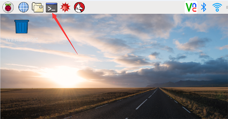
Click on the black icon, which represents terminal, on the top left:
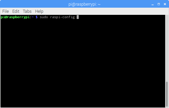
A terminal now pops up. Run sudo raspi-config:
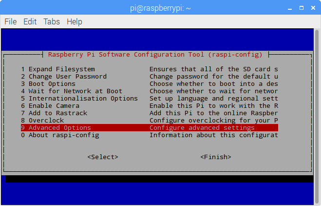
Select Advanced Options by pressing the up/down arrow key:
Press Enter.
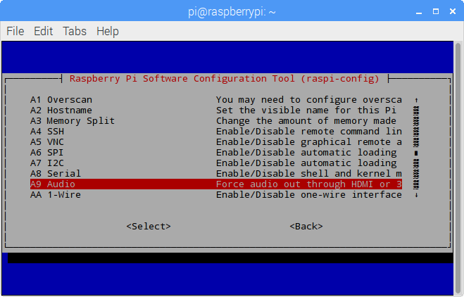
Next, on the pop-up window, select Audio in the same way:
On the window Choose the audio output, select Force HDMI:
Press Enter.
Then return to the main menu and select Finish with the left/right key and press Enter to confirm and exit.
Now the speaker of the monitor should make sounds. Try to play a video on YouTube!
Note: If it still make no sounds, you may need to raise the volume of the monitor and Raspberry Pi.
Free Support
If you have any TECHNICAL questions, add a topic under FORUM section on our website and we'll reply as soon as possible.
For NON-TECH questions like order and shipment issues, please send an email to service@sunfounder.com. You're also welcomed to share your projects on FORUM.
Copyright Notice
All contents including but not limited to texts, images, and code in this manual are owned by the SunFounder Company. You should only use it for personal study, investigation, enjoyment, or other non-commercial or nonprofit purposes, under the related regulations and copyrights laws, without infringing the legal rights of the author and relevant right holders. For any individual or organization that uses these for commercial profit without permission, the Company reserves the right to take legal action.
