Stepper Motor Servo Robot Expansion Board for Raspberry Pi
Introduction
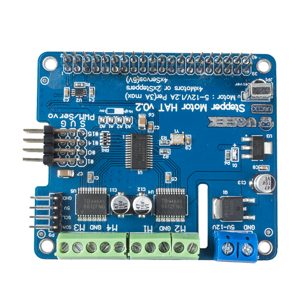
Did you ever dream of creating futuristic projects like maybe a little robot puppy or a cleaner robot of your own? We have just the thing you would need to go wild and explore the field of robotics right in your living space. Meet the Motor/Stepper/Servo all -in -one futuristic extension board. A simple way to drive 4 motors or 2 stepper motors and 4 servos at the same time. But keep the 40 pins of the Raspberry Pi led out, the shield only occupies the I2C pins.
Completely stackable design, 4 address-select pins means there are up to 16 stackable shields, making you do more cooler projects, such as DIY robots, smart car, mechanical arm and intelligent Pan & Tilt and so on.
The Shield requires a 5V~12V supply to power the motor and can power any voltage of the stepper motor. TB6612 MOSFET here works as the motor and stepper motors driver chip that has 1.2A per channel current capability (you can draw up to 3A peak for approx 20ms at a time).
The Shield supports 4-route servo port, 3P standard port and simplifies your connection to 5V servo and LED. The additional infrared receiver sensor makes infrared control a breeze.
We have a fully-dedicated PWM driver chip onboard. This chip handles all the motor and speed controls over I2C. Only two data pins (SDA & SCL in addition to the power pins GND & 5V) are required to drive the multiple motors, and since it's I2C you can also connect any other I2C devices or shields to the same pins.
Feature List
- A single power supply, normal operating power voltage range of 5V~12V. (please choose the correct input voltage according to the voltage the motor requires.)
- Input/output data via RPi's I2C bus
- One-route I2C interface, compatible with 5V level, can be connected to Arduino or other development board to control.
- One-route I2C interface, which can connect various sensors and expand various applications
- The expansion board address is determined by 4 address pins and 16 expansion boards are used at the same time
- Support 16-route PWM channel output
- 12 bit resolution, adjustable PWM frequency up to 1.6KHz, configurable push-pull or open drain output
- Support 4-route servo interface, 3P standard interface, convenient for connecting with 5V steering gear and LED lights
- Support 2-route 6V~12V servo
- Support 4-route 6V~12V deceleration motors
- Support infrared receiving, convenient infrared control
- Size: 65x56x21mm
Preparation
Product List
- 1 x Motor/Stepper/Servo Shield
Required Preparation
- 1. Raspberry Pi 4B
- 2. Servo
Hardware Operation
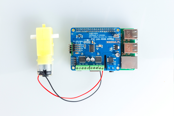
Connect the RPi with the extension board and plug in the servo.
Software Operation
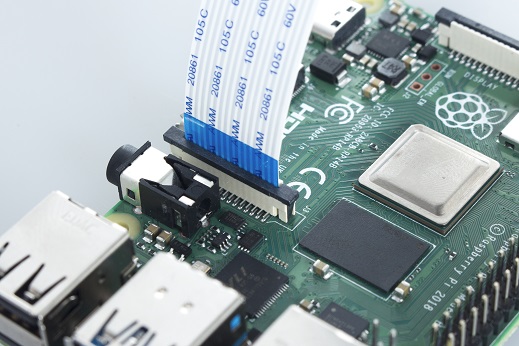
Insert the camera into the Raspberry Pi, lift up the black part here, the blue side of the cable is inserted towards the USB interface of the Raspberry Pi, then press the black buckle
- Click in to access the Raspberry Pi official website https://www.raspberrypi.org/downloads/, and then select to download the image you need according to your compute type(windows/MAC/Ubuntu).
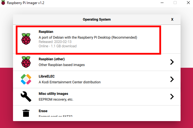
- After downloading, click to start the installation of imager.exe. The RPi Imager page appears when the installation is done. You need to click "CHOOSE OS" then on the new page, select the first one.
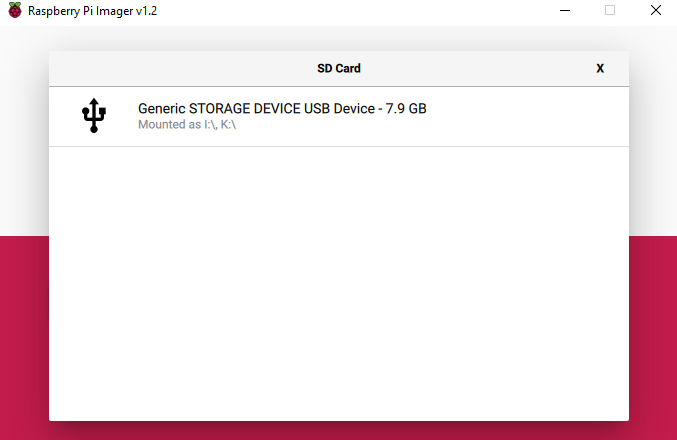
- Insert the SD card in the card reader then plug the card reader into the computer. You should click "CHOOSE SD CARD" to let the following SD Card page appear. Now, select the SD card information bar. Back to the RPi page and click "WRITE" to download and flash the RPi system.
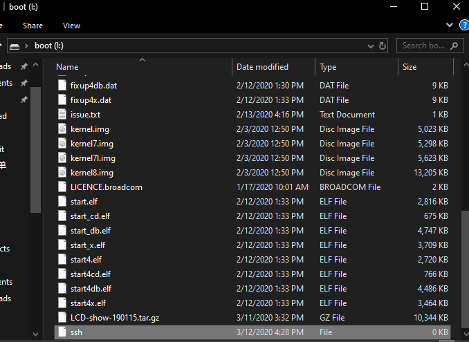
- Replug the card reader once the flash is finished and create a file named ssh without suffix name in / boot directory.
Plug the network cable and the sd card into RPi, then connect the RPi to the power supply.
Now, you can find your RPi ip on the RPi management page.
-
Got the ip, you can use putty tool to control RPi remotely via ssh remote connection.
- putty download link: https://www.chiark.greenend.org.uk/~sgtatham/putty/latest.html
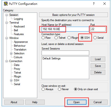
- Download finished, putty page is as shown. You need to input RPi ip, and type in 22 in the port box. Check ssh and click open to connect with RPi.
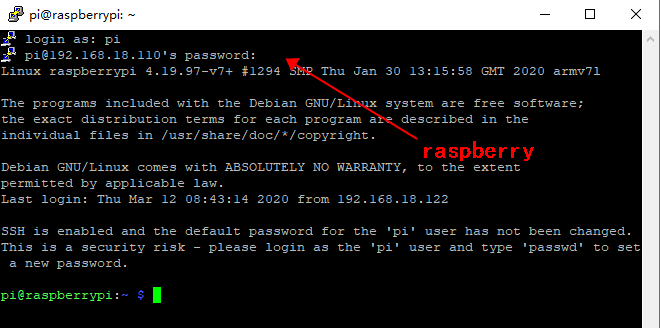
- The terminal page appears once you click open. By default, the ID is "pi" and the password is "raspberry". Note the alphabetic case.
Note: The password characters are hidden when you are entering.
