GYML8511 UV Sensor
Contents
Description
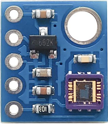
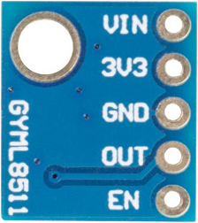
The ML8511 is an UV sensor, which is suitable for acquiring UV intensity indoors or outdoors. The sensor IC applies SOI-CMOS technology so it is widely used in digital circuits and analogy circuits. According to the principle that photocurrent can be converted into voltage, the sensor can detect the UV intensity so it is a good choice for using in an external circuit. ML8511 can output analogy voltage that is proportional to UV intensity.
Applications
Smart phone, Watch, Weather station, Bicycle navigation, Accessary, Gaming.
Features
- Photodiode sensitive to UV-A and UV-B
- Embedded operational amplifier
- Analog voltage output
- Low supply current (300A typ.) and low standby current (0.1A typ.)
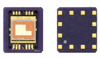
- Small and thin surface mount package (4.0mm x 3.7mm x 0.73mm, 12-pin ceramic QFN)
Introduction of Pins
| Introduction of Pins | |
|---|---|
| VIN | Input terminal of the voltage before getting regulated |
| 3V3 | The anode of the power supply 3v3 |
| GND | The cathode of the power supply |
| OUT | Output (Low in power down or standby mode) |
| EN | Active high enable pin. (High: Active mode, Low: Standby mode) |
Principle
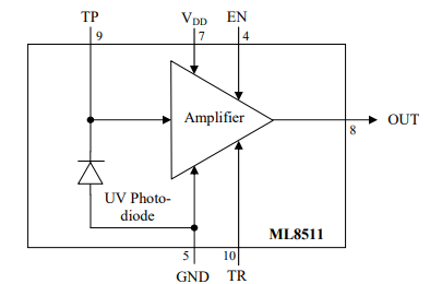
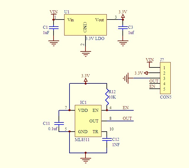
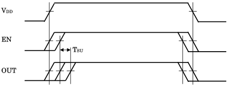
TIMING CHART
Supply voltage and EN signal state should take one of the following procedures:
- EN should be HIGH or LOW at the same time when VDD is applied.
- EN should be HIGH or LOW while VDD is applied.
Output should be read after output voltage level becomes stable. Maximum time is required until stable output voltage reaches 1 millisecond after EN goes HIGH.
Experimental Procedures for Arduino
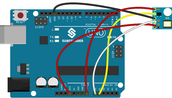
Step 1: Connect the circuit:
//Hardware pin definitions
int UVOUT = A0; //Output from the sensor
int REF_3V3 = A1; //3.3V power on the Arduino board

void setup()
{
  Serial.begin(9600);

  pinMode(UVOUT, INPUT);
  pinMode(REF_3V3, INPUT);

  Serial.println("MP8511 example");
}

void loop()
{
  int uvLevel = averageAnalogRead(UVOUT);
  int refLevel = averageAnalogRead(REF_3V3);

  //Use the 3.3V power pin as a reference to get a very accurate output value from sensor
  float outputVoltage = 3.3 / refLevel * uvLevel;

  float uvIntensity = mapfloat(outputVoltage, 0.99, 2.9, 0.0, 15.0);

  Serial.print("MP8511 output: ");
  Serial.print(uvLevel);

  Serial.print(" MP8511 voltage: ");
  Serial.print(outputVoltage);

  Serial.print(" UV Intensity (mW/cm^2): ");
  Serial.print(uvIntensity);

  Serial.println();

  delay(100);
}

//Takes an average of readings on a given pin
//Returns the average
int averageAnalogRead(int pinToRead)
{
  byte numberOfReadings = 8;
  unsigned int runningValue = 0;

  for(int x = 0 ; x < numberOfReadings ; x++)
    runningValue += analogRead(pinToRead);
  runningValue /= numberOfReadings;

  return(runningValue);
}

//The Arduino Map function but for floats
//From: http://forum.arduino.cc/index.php?topic=3922.0
float mapfloat(float x, float in_min, float in_max, float out_min, float out_max)
{
  return (x - in_min) * (out_max - out_min) / (in_max - in_min) + out_min;
}
