Ethernet Shield W5100
Ethernet Shield W5100
Introduction
The W5100 is a versatile single-chip network interface chip with a 10/100Mbs Ethernet controller integrated internally. It is mainly used in a high integrated, high stable, high performance and low cost embedded system. The W5100 enables you to connect to the Internet without operation system. It is also compatible with IEEE802.3 10BASE-T and 802.3u 100BASE-TX.
W5100 integrates a market-proven full-hardware TCP/IP protocol stack inside, Ethernet media access control (MAC) layer and physical layer (PHY). The hardware TCP/IP protocol stack supports the following protocols: TCP, UDP, IPV4, ICMP, ARP, IGMP and PPoE, which have been tested by the market for years in many fields. In addition, W5100 also integrates 16KB memory for data transmission. For W5100, you don't need to consider the control of the Ethernet; what you need to do is socket programming.
The W5100 has three interfaces: direct parallel bus, indirect parallel bus and SPI bus. It is easy to connect it with an MCU, just like accessing an external memory. Here we use the Ethernet library to apply W5100 more easily and conveniently.
Features
1) With this Ethernet Shield, your Arduino board can be used to connect to the Internet.
2) Can be used as server or client.
3) Directly plug puzzle board, no soldering required.
4) Controller: w5100.
5) This is the latest version of the Ethernet Shield.
6) Based on the Wiznet W5100 Ethernet Chip, the shield gives you an easy way to get your Arduino online.
7) Directly supported by Arduino official Ethernet Library.
8) Adds a micro-SD card slot, to store files for serving over the network.
9) Compatible with the Arduino Duemilanove (168 or 328), Uno as well as Mega (1280/2560), accessible using the SD library.
10) The Wiznet W5100 provides a network (IP) stack capable of both TCP and UDP.
11) Supports up to four simultaneous socket connections.
12) Uses the Ethernet library to write sketches which connect to the internet using the shield.
13) Fits all version of arduino Main board,2009,UNO, mega 1280, mega 2560.
14) Size: 7 x 5.4 x 2.4 cm (2.76 x 2.12 x 0.94 inch).
DeviceBit Platform
To test the performance of the W5100 shield, you need to know a real-time data brokerage platform - DeviceBit platform. Upload the data collected by sensors to DeviceBit through the W5100, and you can then DIY a mini smart home system.
Introduction
The DeviceBit platform (http://www.devicebit.com/home/publicsensors) is a real-time data brokerage platform for the Internet of Things (IoT), providing most of its functionality via its Application Programming Interface (API). It is quick and easy to add Devices and Applications to the DeviceBit platform. It provides real-time data storage and remote control at scale. The DeviceBit platform is not just an easy way to prototype new Internet-enabled sensors; it's also a service that helps companies bring products to market at scale.
The DeviceBit platform provides basic data analysis tools for rapid data evaluation, as well as real-time alerts and notifications if sensors report “abnormal” conditions.
You can realize your own ideas and develop your own devices relying on this platform. You can focus on hardware instead of software infrastructure.
The DeviceBit platform also communicates with existing social network, such as Twitter and Facebook, allowing you to share what you do with your friend, which might be very helpful to their research on similar field.
Operate on DeviceBit Platform
Register an Account on DeviceBit
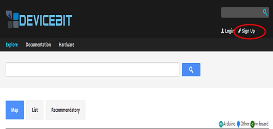
Log in on the website (http://www.devicebit.com/). Click Sign Up on the top right corner of the page.
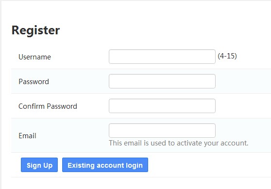
The following page will appear, enter your username, password, and Email. Then log into your mailbox to activate your account.
Add a New Device
Log in to your account,then go to User Center, and go to My Devices -> Devices -> Add A device.

Fill in the related information and then click Save.
The related parameters are explained as follows:
1) ID: The ID of the device, allocated by system automatically. It is unique for each device.
2) Type: The type of the device. Click the inverted triangle and the following options will appear.
Arduino: Arduino Board.
Lw-board: The board developed by DeviceBit.
Other: Other boards.
3) Name: The name of the device. For example, Smart Home
4) Description: Description of the device.
5) Public: If your devices are public, other users can also view them and their measurement.
6) Location: The location of your device. Click the location point on the Map.
Add a New Sensor
The next step is to add a new sensor connected to your device.
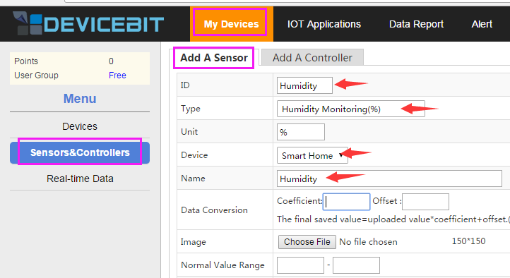
Go to My Devices -> Sensors&Controllers -> Sensors, and then click Add to create a new sensor.
Now, the following page will appear:
Fill in the related information and then click Save.
The related parameters are explained as follows:
1) ID: The ID of the new sensor. It is unique for each sensor.
2) Type: The type of the new sensor.
3) Unit: The unit of the measurement.
4) Device: Select the device which the sensor is to be connected to.
5) Name: The name of the new sensor.
6) Data Conversion: To calibrate your sensor’s measurement. You can enter Coefficient and Offset if applicable.
7) Picture: Upload the picture of your sensor.
8) Public: If your sensors are public, other users can also view them and their measurement.
9) Normal range: The normal range of the sensor’s measurement. You can set it according to your actual need.
10) Overrange alarm: Turn it on and you will receive the alert by SMS or email when the sensor’s measurement is out of the range.
11) Data post period: The system indicates that the sensor is OFFLINE if it does not get the data posted by the sensor within every data post period set here.
12) Remark: Remark of the sensor.
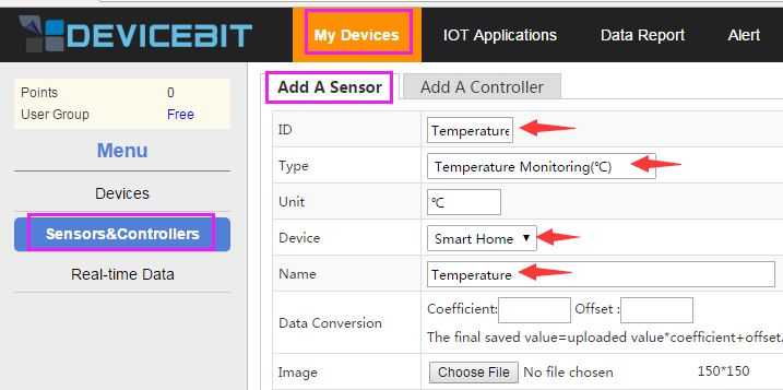
Similarly, add another sensor - Temperature.
Ethernet Shield W5100 Test
Preparations
- 1 x Network cable
- 1 x Ethernet Shield W5100 Module
- 1 x Sensor module (e.g. Humiture sensor module)
- Several jumper wires
- 1 x Mega2560 Board (or Uno Board)
Procedures
Build the circuit
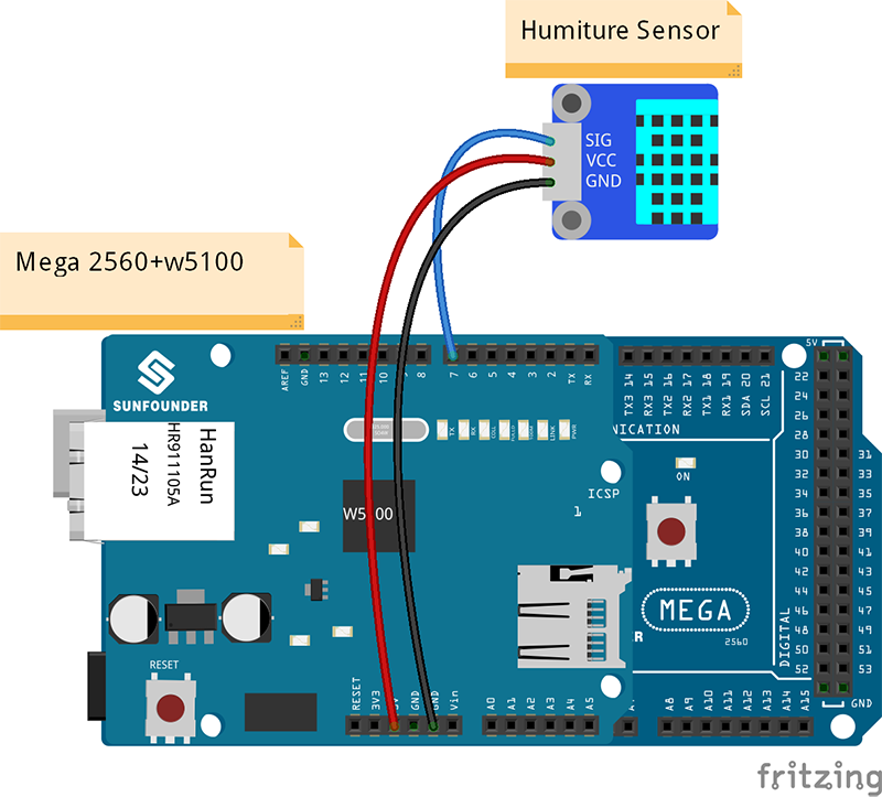
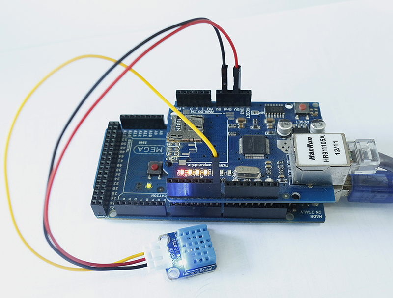
Connect the devices just like the image below. Then connect the Mega2560 to the computer via a USB cable, the W5100 to the router via a network cable.
Add Libraries
Download Humiture_sensor.zip, unzip it. Under Humiture_sensor\Library, there are two libraries DeviceBitTcpClient and Dht11, which you need to add to the Arduino/libraries.
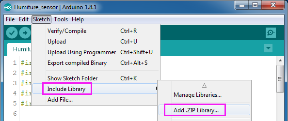
Double click to open the Humiture_sensor.ino file, select Sketch -> Include Library -> Add .ZIP Library.
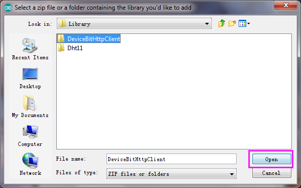
Find the folder and select DeviceBitHttpClient, click Open.
If a prompt "Library added to your libraries.Check”Include library”menu" appears at the bottom of the window, it means the library is added successfully.
In the same way, add the Dht11 library.
Modify LW_USERKEY and LW_GATEWAY
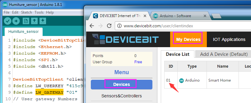
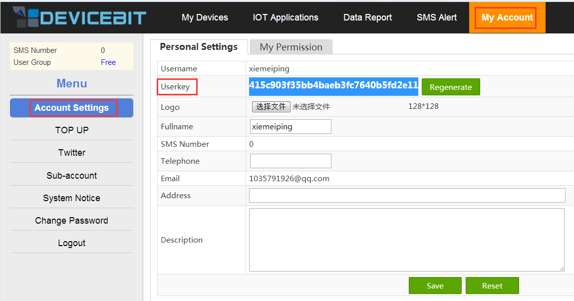
You need to change the value of LW_USERKEY and LW_GATEWAY into your own in the code.
Upload the code to Mega2560
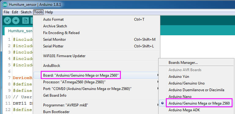
Select the correct board:
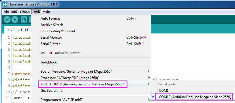
And port:
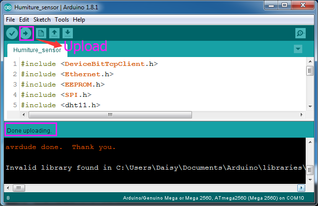
Click the Upload icon to upload the sketch:
View the Data
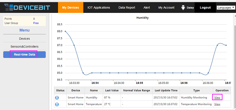
Click Real-time Data and you can see the data has been uploaded, and Status of the sensor changes from grey to blue. Click View to view the data curve.
Also you can visit m.devicebit.com on your mobile phone to enter into the DeviceBit platform. The operations are similar to those on the PC.
