6D-BOX FAQ
Contents
[hide]Q1: How to Connect the Drone 6D-BOX and Receiver FlySky FS-iA6
Since the 6D-Box quadcopter kit does not include the receiver and radio transmitter, you may need some instructions on how to apply them with the kit. Here’s some guide on connecting the drone and receiver. (For more information, please refer to our user manual for the kit under LEARN.)
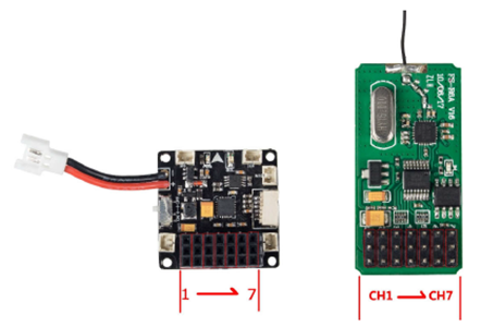
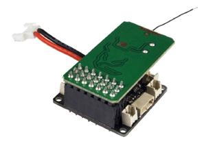
A: If the CH1 of your receiver is the leftmost and there are 1 to 7 channels, just insert the CH1 pin on the receiver into the No.7 pin header on the flight controller, CH2 to No.6 ,CH3 to No.5, Ch4 to No.4, CH5 to No.3, Ch6 to No.2 and CH7 to No.1 as shown below.
Note: B/VCC of the receiver is the channel for pairing and power input and will not function after connecting to the 6D-BOX.
Check the following instructions for using the B/VCC channel
The binding of the receiver with the transmitter is already done when it's manufactured. So you DO NOT need to bind again. But if you want to use them with other radio transmitters or receivers, then you need to re-bind. Please take the following steps before further operations:
1. Install the battery to the transmitter and shut it down.
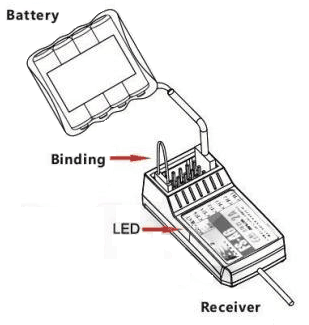
2. Insert the binding cable into the B/VCC channel port of the receiver.
3. Connect the battery to any channel to power the receiver. When the red light indicator LED on the receiver blinks, it means they are binding now.
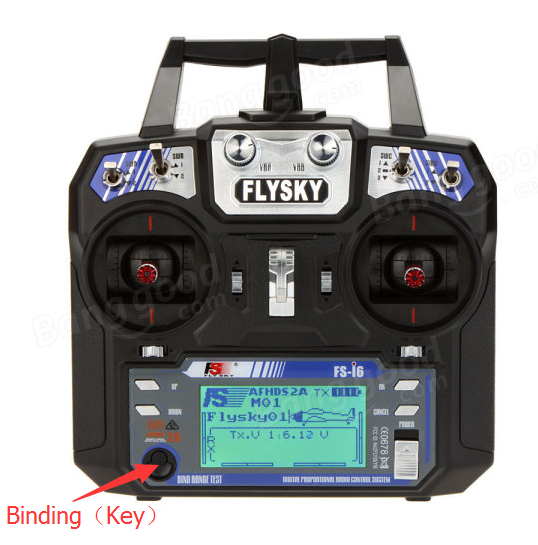
4. Press and hold the Binding (Key) on the transmitter and switch on the transmitter at the same time.
5. If the red indicator stops blinking, it means the binding is done successfully.
6. Then disconnect the power of the receiver.
7. Shut down the transmitter.
8. Connect the receiver and the flight control to check whether the binding is successful. If not, please take these steps again carefully to do it right.
Q2:The file "javaw.exe" could not be found. Verify that the filename is correct, then try again.
Edited based on the original article from stackoverflow.com: https://stackoverflow.com/questions/14004851/javaw-exe-cannot-find-path
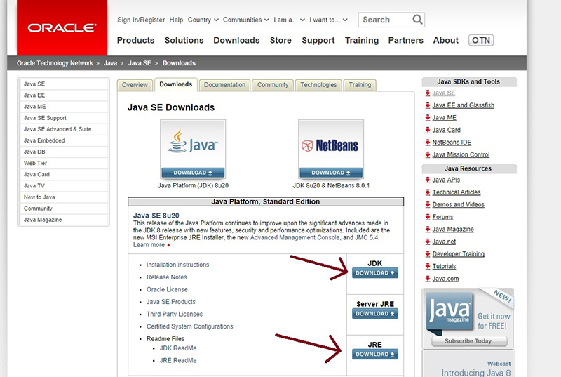
A: Make sure to download these from: http://www.oracle.com/technetwork/java/javase/downloads/index.html
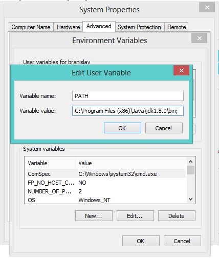
Also create PATH environment variable on your computer like this (if it doesn't exist yet):
1. Right click on My Computer/Computer
2. Properties
3. Advanced system settings (or just Advanced)
4. Environment variables
5. If the PATH variable doesn't exist among "User variables", click New (Variable name: PATH, Variable value: C:\Program Files\Java\jdk1.8.0\bin; please check out the right version, which may differ as Oracle keeps updating Java); in the end, enable the assignment of multiple values to PATH variable.
6. Click OK! Done
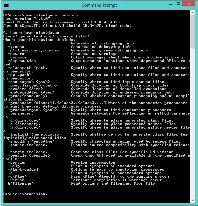
To be sure that everything works, open CMD Prompt and type: java -version to check for Java version and javac to be sure that compiler responds.
Hope this helps. Good luck!
Q3: 6D-BOX drone doesn’t fly over 10cm.
A:
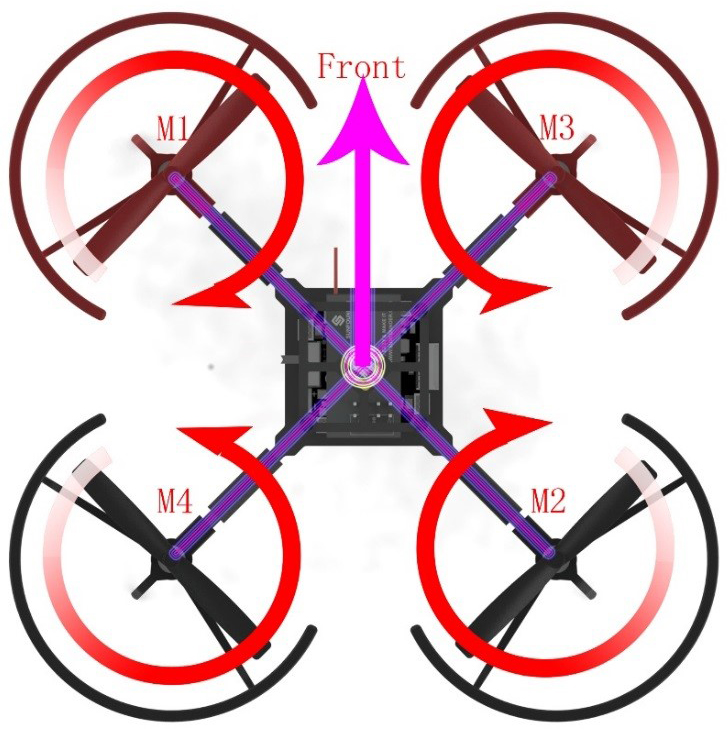
1. Ensure motors move in correct directions.
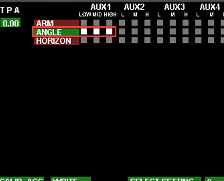
2. Check if your drone is in Stabilize Mode. If it is not, please click LOW, MID and HIGH on the row ANGLE as the screenshot below.
Then please refer to the manual on page 14-15 on the part 3.6 Configure Flight Parameters in GUI to write data to your flight controller board.
3. Calibration is needed every time the flight controller board is powered on. For specific calibration steps, please view the part 4.3 Gyroscope and Accelerator Calibration on page 24 of the manual.
Q4: One channel of some transmitters fails.
A:
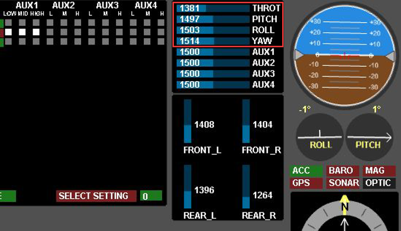
Method 1: Test each channel and observe if corresponding values change on the host computer.
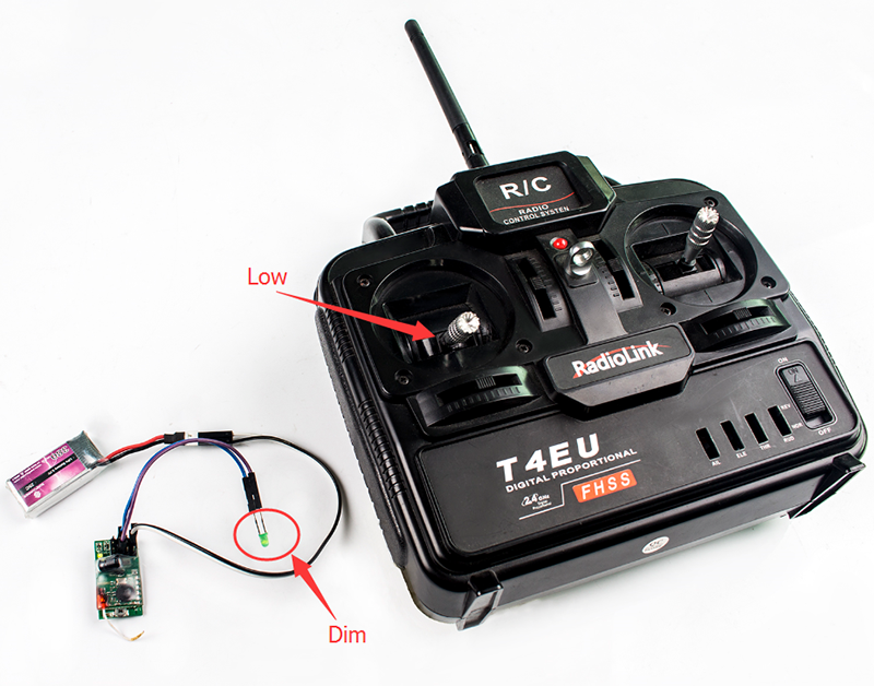
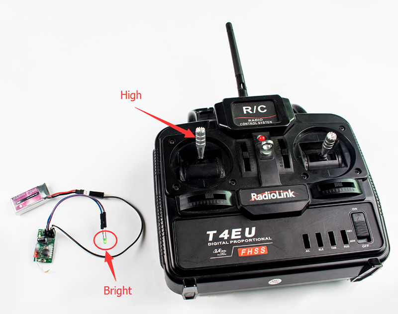
Method 2: Test if each channel works properly with simple circuit connection.
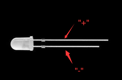
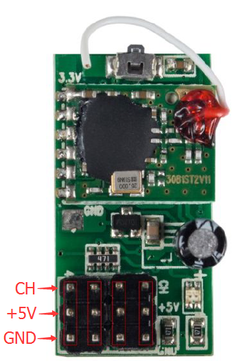
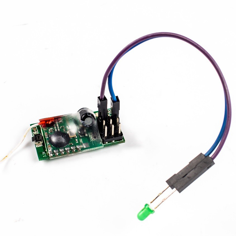
1. separately connect two female dupont wires to LED. (Note: LED's long pin is positive pole; the short pin is negative pole.) Plug the female dupont wire that is on LEDs positive pole in CH2 port of the receiver, and plug the dupont wire that is on LED's negative pole in a GND port on the receiver.
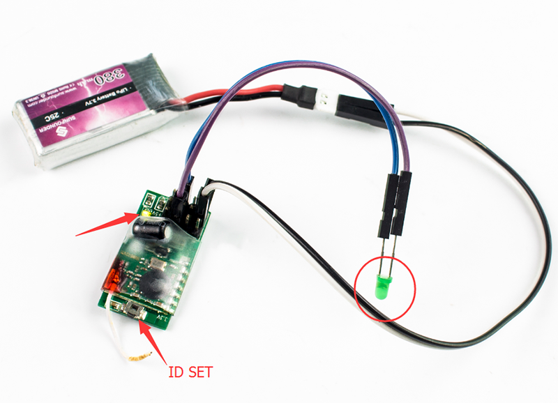
2. Connect two male to female dupont wires to the +5V and GND port on the 6D-Box receiver. Plug the dupont wire connecting to +5V in the battery's positive pole; plug the GND cable in the negative pole. At this time, the green light on receiver is on, while LED is off.
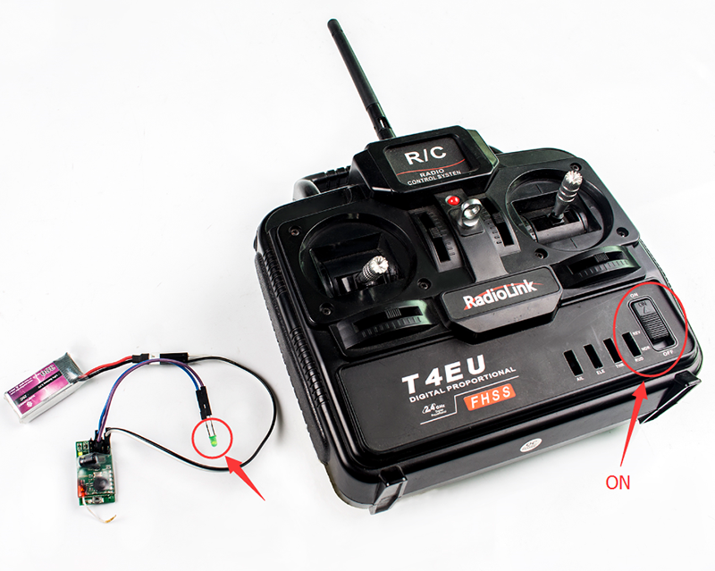
3. Turn on the power switch, and then press the ID SET matching button on receiver for a few seconds. After the green light on receiver doesn't flash any more that means code matching is successful. (Note: Ensure LED and dupont wires are properly connected and are constantly lit up). If LED doesn't light, code matching may fail, and please re-match code. If the LED doesn't light after multiple tries, please plug the wire that connects LED's postive pole in the channel CH1 / CH3 / CH4 on receiver. And please make sure contacts of LED and dupont wires are in a good condition. If the LED still doesn't light, that means the receiver is defective.
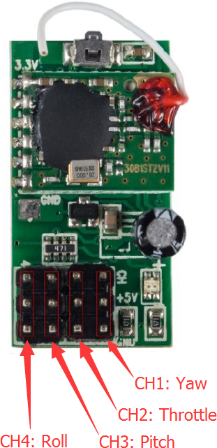
4. When LED is in constantly on status, slowly push throttle (in the position CH2 in the picture below) from the minimum to the maximum, if LED changes from dim to bright, that means channels work correctly. (It is suggested to do in a dim environment.)
5. Connect the DuPont wire on the LED's positive pole to channel CH1 / CH3 / CH4 of the receiver and repeat step 4. Check if channels work correctly, and please carefully observe the LED brightness changes. If one of channels couldn't control LED brightness, receiver is partially defective then.
