BMP280 Pressure Sensor Module
Note: Since the BMP280 comes with a higher performance, we have updated the BMP180 to BMP280 in the kit to provide a better experience for the customers, here is the manual:
Contents
Introduction
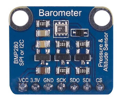
The BMP280 Digital Barometer is developed by Bosch Sensortec. Compared with the previous BMP085, BMP180, and BMP183, this BMP280 barometer comes with a higher performance and the smallest size in the industry.
The BMP280 is an absolute barometric pressure sensor especially designed for mobile applications. The sensor module is housed in an extremely compact 8-pin metal-lid LGA package with a footprint of only 2.0x2.5mm2 and 0.95mm package height. Its small dimensions and low power consumption of 2.7µA@1Hz allow the implementation in battery-driven devices such as mobile phones, GPS modules or watches. It supports two types of communication: I2C and SPI.
Principle
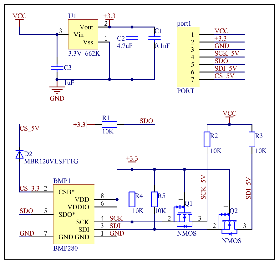
The schematic diagram of the module:
Power
• VCC: power pin. The working voltage for the chip is 1.71-3.6V. Since the module integrates a 3.3V voltage regulator, the power supply can be either 3.3V or 5V. If you are using an Arduino board, you're recommended to use a 5V power supply.
• 3.3V: the output of the voltage regulator, meaning you can provide the chip with a 3.3V for power here.
• GND: common ground for power and logic.BMP280 supports I2C and SPI communication and the module keeps both ports. If you want to connect a simple circuit, you can use the I2C port; to connect multiple sensors, you can use the SPI port free of I2C address collisions.
I2C interface
The I2C interface uses the following pins:
• SCK: serial clock (SCL)
• SDI: data (SDA)
• SDO: The I2C address decides the pin. If SDO connects to GND(0), the address is 0x76, if it connects to VDDIO(1), the address is 0x77. In this module, we have connected it to VDDIO, so the address should be 0x77.
• CSB: Must be connected to VDDIO to select I2C interface.
SPI interface
The SPI interface uses the following pins:
• CSB: chip select, active low and has an integrated pull-up resistor
• SCK: serial clock
• SDI: serial data input; data input/output in 3-wire mode
• SDO: serial data output; hi-Z in 3-wire mode
Experimental Procedures
BMP280 for Arduino
Components
- 1 * SunFounder Uno board
- 1 * USB Cable
- 1 * BMP280 Module
- Several jump wires
- 1* Breadboard
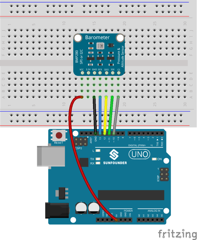
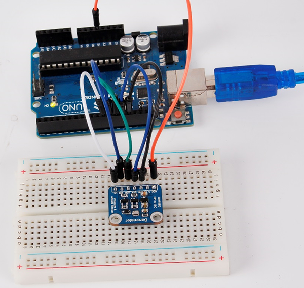
Step1: Build the circuit
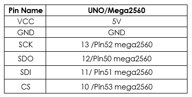
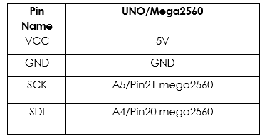
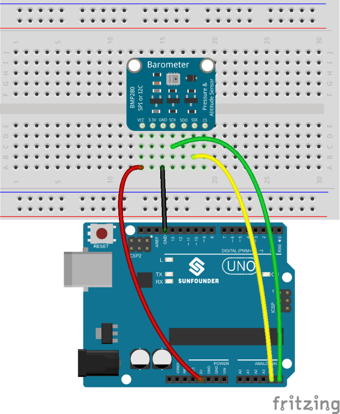
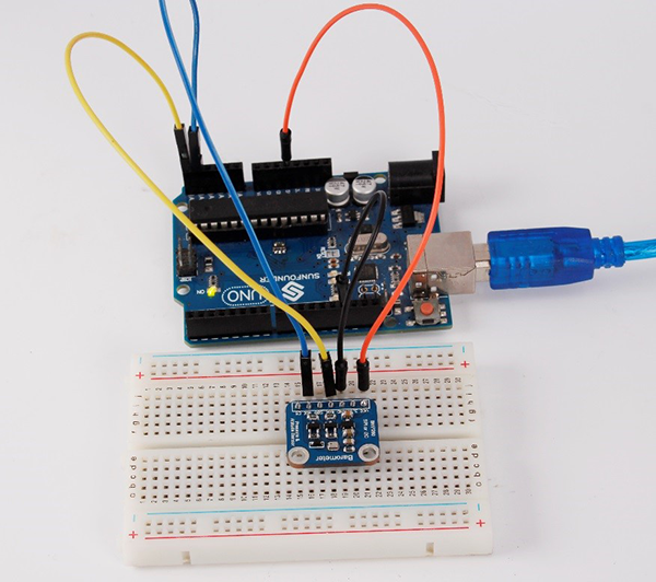
You can connect in the following two ways: I2C and SPI, those two ways will be a little different on the Uno R3 and the Mega2560 (as shown below), taking Uno R3 as an example, choose one way and connect successfully, you can move to the next step then
I2C wiring
Step 2: Add library to the Arduino/ libraries folder
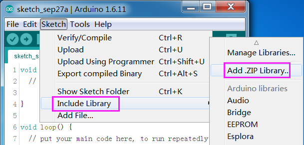
Click Sketch -> Include Library ->Add ZIP Library
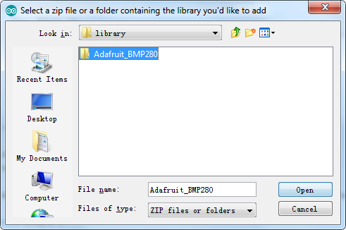
Find Adafruit_BMP280 under BMP280\Arduino code BMP280\library, click open to add it.
Step 3: If you use the I2C way for connecting, double-click BMP280_I2C.ino under BMP280\Arduino code BMP280\Code\BMP280_I2C to open it; if you use the SPI way, please double-click BMP280_SPI.ino under BMP280\Arduino code BMP280\Code\BMP280_SPI to open it.
Step 4: After choosing the correct board and port, upload the code to the board.
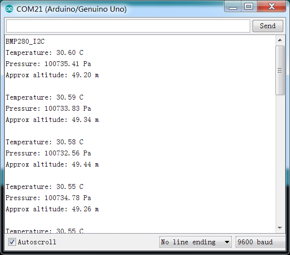
Step 5:Open the serial monitor, you will see the figures of the temperature, the air pressure and the sea-level altitude.
