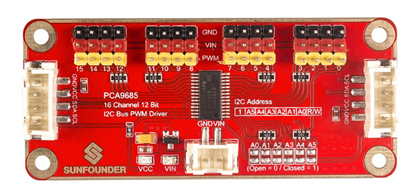
PCA9685 16-Channel 12 Bit I2C Bus PWM Driver
Introduction

The PCA9685 is an I2C-bus controlled 16-channel LED controller optimized for Red/Green/Blue/Amber (RGBA) color backlighting applications. Each LED output has its own 12-bit resolution (4096 steps) fixed frequency individual PWM controller that operates at a programmable frequency from a typical of 24Hz to 1526Hz with a duty cycle that is adjustable from 0 % to 100 % to allow the LED to be set to a specific brightness value. All outputs are set to the same PWM frequency.
This PWM Servo Driver uses the chip PCA9685 for control. With only 2 pins, it can drive 16 servos, which greatly reduces the I/O occupation. In addition, you can connect up to 62 driver boards in a cascading way, thus amazingly driving 992 servos in total.
Features
>A PWM Driver with I2C interface
>Controls 16 PWM output channels with only 2 pins, and connects 62 >driver boards at most in a cascading way to drive up to 992 PWM output channels
>The base of pins on the board to connect servo wires are paint in 3 colors for easy recognition, so you can plug in the wires correctly at the first sight by color.
>Supports max 12V for external power supply; with a power indicator
12-bit resolution for each output - for servos, that means about 4us resolution at 60Hz update rate
>Frequency: 40-1000Hz
>Channel number: 16 channel
>Resolution: 12 bit
>Voltage: DC 12V (Max)
>Size: 74 x 32 mm
Principle
The driver module uses the PCA9685 chip as control and can output 16 channels of PWM signal. You can program the control chip to set the PWM frequency and duty cycle of each channel so as to accurately control servos. The turn-on time of each LED driver output and the duty cycle of PWM can be controlled independently using the LEDn_ON and LEDn_OFF registers.
If we set the time of LED_ON as 409, the time span for LED_OFF would be 1228, and the duty cycle of PWM be: (1228-409/4096) x 100% = 20%.

How a servo works: PWM signals go into the signal demodulation circuit through the receiving channel, so to generate a DC bias voltage. It will then be compared with the voltage of the potentiometer, and thus a voltage gap is obtained and input into the motor driver IC to drive the motors to rotate clockwise or anticlockwise. When the speed reaches to a certain number, it will drive the potentiometer R to rotate by the cascaded reduction gear, until the gap is reduced to 0 and the servo stops spinning. A servo is controlled by PWM signals, and the change of duty cycle control that of the position the servo rotates to.