SF250 FAQ
Kit
Q1:Calibrated the motors but the no1 does not spin costantly..I have to put throttle to 50% or more and it starts..but when i go down to 10-20% it stop
A: Does the same happen to the rest three motors? If just the No.1 motor did not spin at low throttle, you can debug it as follows.
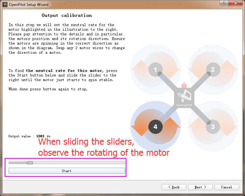
1) It may be idle speed (RPM) not being set. You can set the value like this:
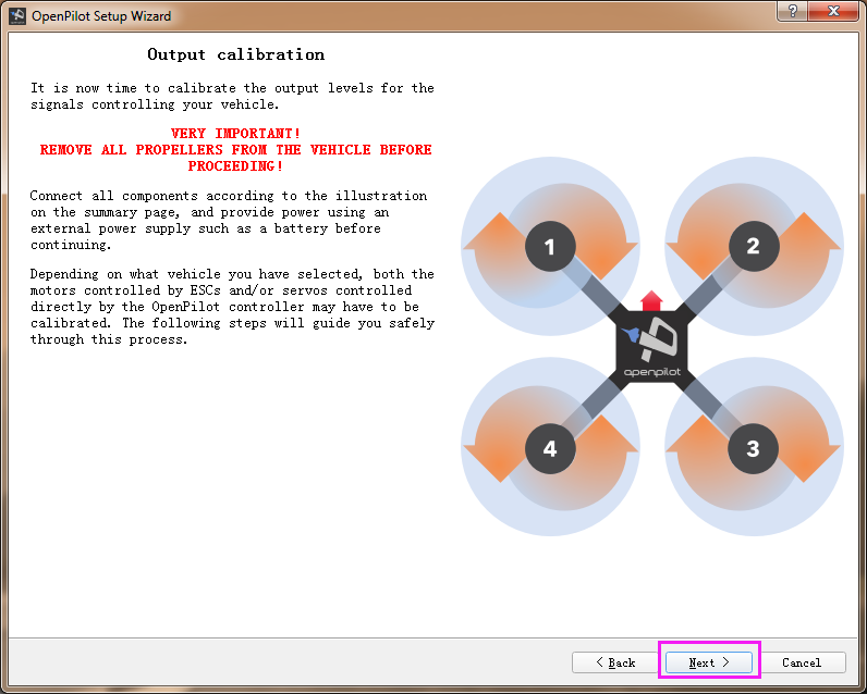
The output calibration means setting the neutral rate for the motor. Follow the steps below:
Step 1: Connect the battery to the aircraft.
Step 2: Press the Start button below and slide the slider to the right until the motor starts to spin.
Step 3: click Stop. When the motor stops, press Start again to see whether the motor can start itself. Slide the sliders to the left or right to set the critical point of the motor to spin.
Step 4: Please pay attention to the rotation direction of the motor. Ensure the motors are spinning in the correct direction as shown in the diagram. Swap any two wires of a motor to change the direction.
Since the output calibration of the Motor 2, 3 and 4 is the same as the Motor 1, just set their neutral rate in the same way as setting the Motor 1.
Note: Pay attention NOT TO make the motor spin too slowly because it will give out much heat at the critical point, which may damage the motor.
2) Possibly the throttle travel is not set of the ESC. Refer to the following steps to set the travel of the ESC connected to the No.1 motor.
Test Operations (power-on):
1. Ensure the receiver is in PWM mode. About shifting the receiver’s mode, please follow the instructions.
2. Connect the signal wire of the ESC to the pin 3 of the receiver, i.e., the yellow wire to pin S, red one to +, and black one to -.
3. Power on the radio transmitter → pull throttle to max → power on ESCs → detects a max throttle signal → beep twice, indicating the max throttle is set and saved → pull throttle to min within 2 seconds → a long beep indicates the min throttle signal is detected → check the battery’s voltage, beep three times, indicating the cells quantity of battery → hear the notes “♪ 1 2 3”, indicating it’s ready → pull up the throttle to start → pull up a little to see whether the motor spins or not.
4. Repeat the operations above to configure the rest motors and ESCs.
Check the Test Video here: https://www.youtube.com/watch?v=3aV-8cS6D_I
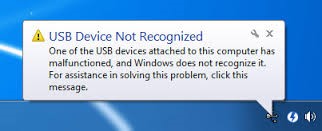
Q2:Unrecognized Hardware Issue for CC3D
Q: It happens that your CC3D board may not be recognized by the computer. Now let's check how to solve the problem - re-flash the bootloader and hardware
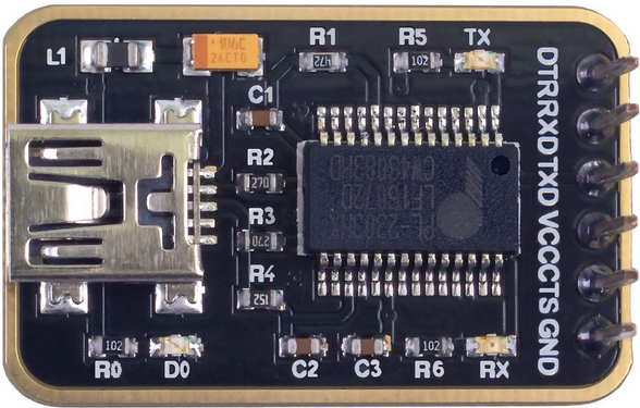
Preparations
1.Flash Loader Demonstrator

2.The PL2303 Mini USB to UART board
Bootloader
Step 1: Wiring
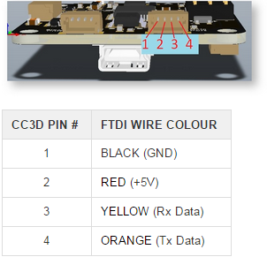
Step 2: Connect the 3.3V and SBL on the CC3D board as shown below. You can do it by some metal tool.
Then take the rest actions based on the following instructions.
Download the CC3D bootloader.zip,CC3D bootloader.zip,unzip it and install the Flash Loader Demonstrator in the folder.
Open the Flash Loader Demonstrator, as shown blow:
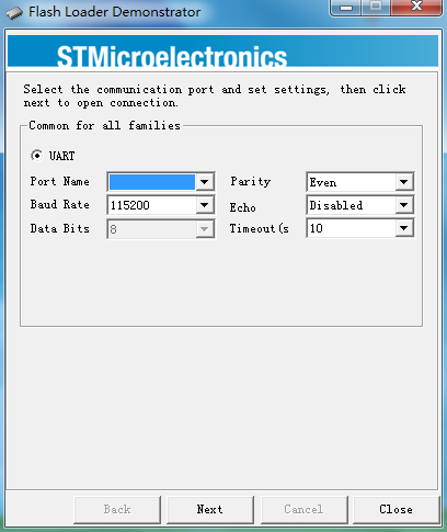
1. Cut off power.
2. Connect the SBL and 3.3V of CC3D for now, power it on.
3. Select the correct port and Click Next.
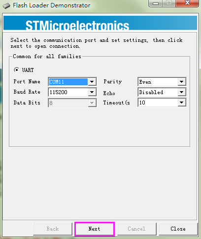
If this interface appears, it indicates that you've connected them successfully.
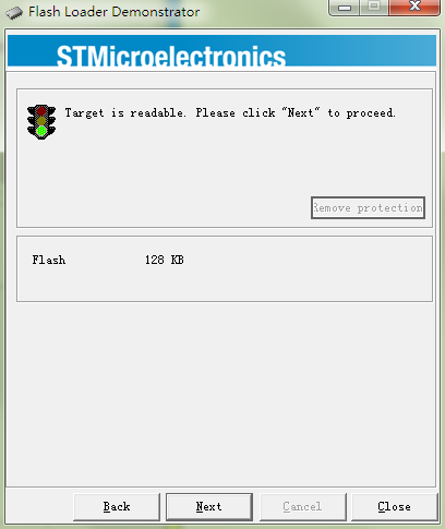
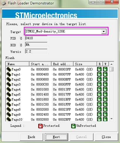
Check here and ensure that it's STM32_Med-density_128K
Click Erase first to erase the original bootloader
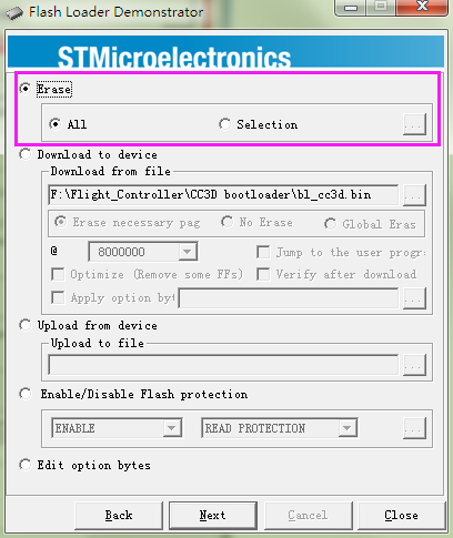
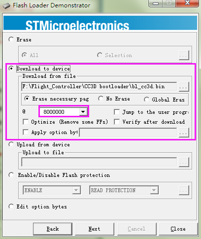
Click Back, Select Download to device.
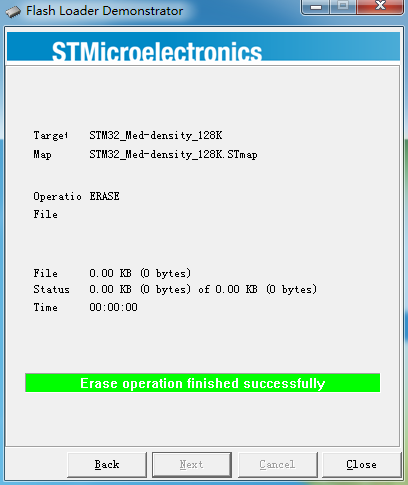
Under Download from file, choose 8000000 which is the area of the bootloader.
Under Download from file, click the browse button and find the bl_cc3d.bin file in the unzipped CC3D bootloader.zip folder, select it and click Open.
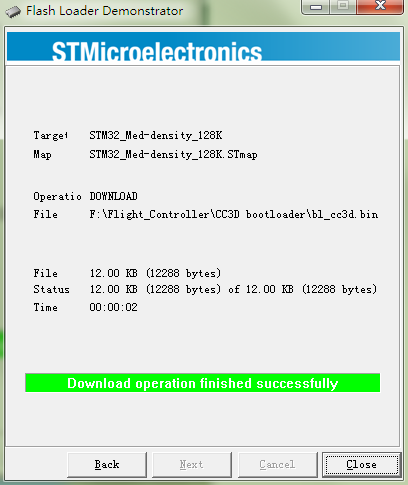
Click Next for download (processing as shown below):
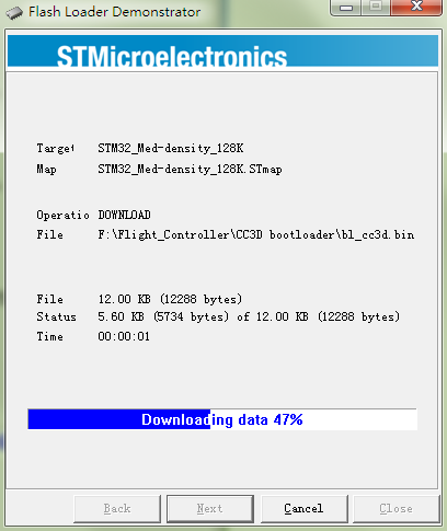
So now the Bootloader for CC3D is downloaded successfully.
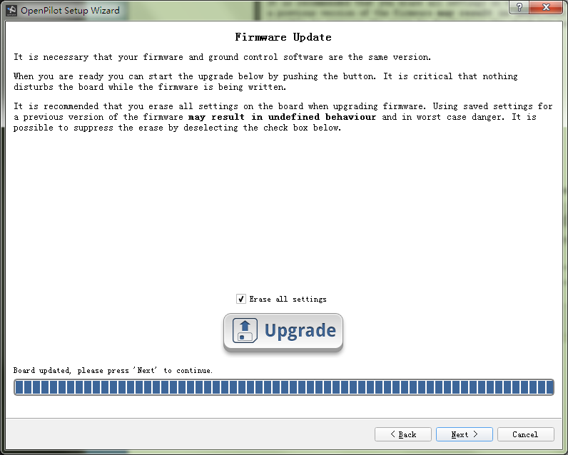
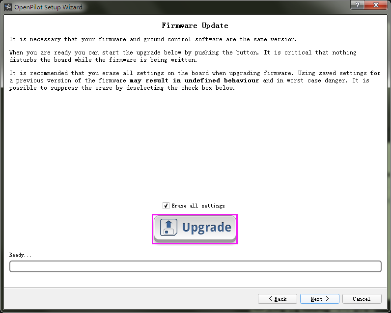
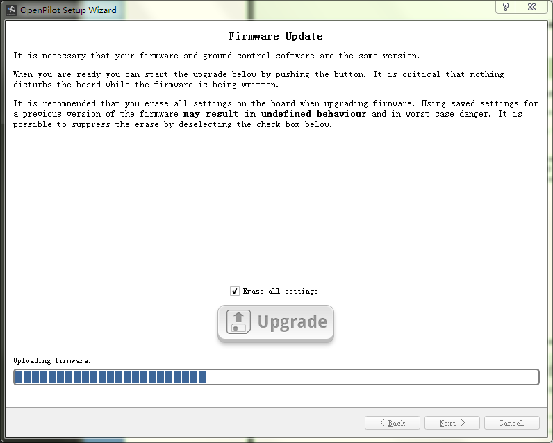
Firmware Update
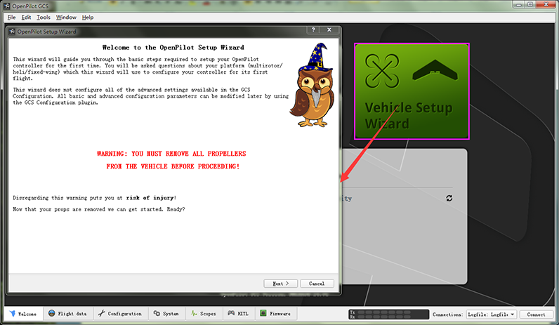
Open the installed OpenPilot GCS on your computer.
Click Vehicle Setup Wizard.
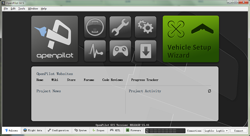
When the following window appears, connect the CC3D flight control to the computer via a USB cable.
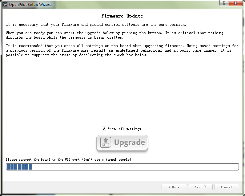
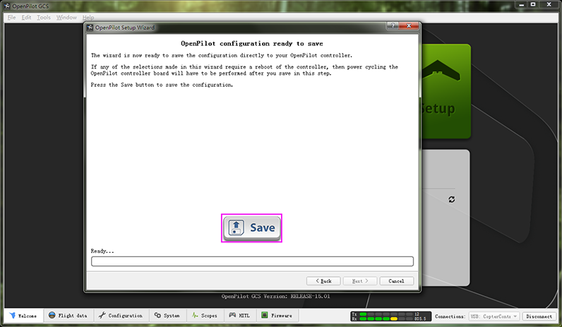
Click Next and finish the setting based on the CC3D user manual.
