SF Racing F3 flight controller
About the SF Racing F3
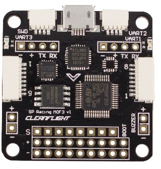
The SF Racing F3 flight controller is designed to provide high performance flight experience for the hobbyists. With verified sensor algorithm, it provides incomparable I/O capabilities. The SF Racing F3 runs a next-generation 32-bit STM32F303CCT6 processor, an MPU6500 accelerometer and a gyroscope sensor, all high integrated on a lightweight PCB to improve the flight performance. In addition, it offers more practical functions to your aircraft. The SF Racing F3 flight controller is perfect whether you are doing FPV contest or practicing stunt flying and it is suitable for a variety of aircrafts including tricopters, quadcopters, hexacopters, octocopters, fixed wing aircrafts, etc.
Features
1. The next-generation processor STM32F3 supports high performance floating-point arithmetic and faster calculation by the ARM Cortex M4 kernel. The looptime for the flight controller is about 2 times of the previous STM32F1.
2. The functions of the I/O ports in the flight controller can be greatly extended and these ports can be used simultaneously for connecting various devices such as OSD, Smartport, SBUS, GPS, LED light strip, battery monitor, buzzer, and eight motors.
3. The sixteen PWM I/O cables serve for ESCs, servos and traditional receivers, among which eight cables work with standard pin headers and the others are distributed in the connectors of the flight controller.
4. It supports SBUS, SFektrum1024/2048, PPM, PWM and XBus receivers and needs no external inverter with one already built in.
5. It fully supports the OneShot ESCs for easy PID tuning.
6. The dedicated programmable LED light strip provides a variety of signal lights for the aircraft heading, racing and night flight.
7. It includes a SFecific I2C port to connect an OLED diSFlay, needless of extra batteries.
8. It provides a battery monitoring port for voltage and current.
9. The buzzer raises the alarm and sends out notification so you can search for the lost aircraft.
10. You can choose from serial wire debug (SWD) and boot mode, so the bootloader will not be locked.
11. It uses pin headers, JST-SH sockets or solder pads to wire up. Both angled and straight pin headers are available.
12. It works with a variety of aircrafts like tricopters, quadcopters, hexacopters, octocopters, planes, etc.
13. Configuration of the flight controller can be done via a cross-platform GUI (Windows/OSX/Linux).
Software
The SF Racing F3 runs the open-source Cleanflight flight control software which has an ever-growing community of friendly developers and users. Being open-source means that you can contribute to the system.
Structure Specification
Dimensions: Board sizing 36 x 36 mm with 30.5mm mounting holes.
Weight: 5.8g
The front:
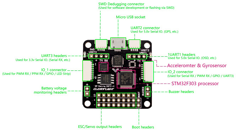
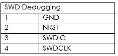
1. SWD debugging connector: To debug the port.
Used for software development or flashing via SWD. It cannot be run when USART2 is in use.
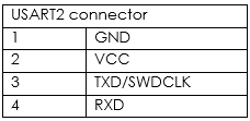
2. USART2 connector: Used for the 5V I/O ports (GPS, etc.). It cannot be run when SWD port is in use.
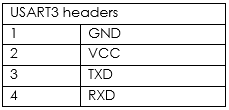
3. USART3 headers: Used for the 3.3 V I/O ports.
It MUST NOT be used when PWM RX is in use or when it's IO_2 CH3/4.
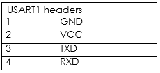
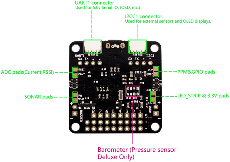
4. USART1 headers: Used for the 5V I/O ports (OSD, etc.). DO NOT use it when the USB port is connected.
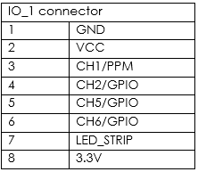
5. IO_1 connector: To connect the PWM RX or PPM RX remote signal mode as well as set the LED and GPIO.
When using the PWM receiver, connect its CH1, CH2, CH5, and CH6 to pin 3-6 (PWM RX) of the IO_1 connector respectively.
Connect it to pin 3 of the IO_1 connector when using a PPM receiver.
The LED light can be set for battery warning, status indication, flight mode display, etc.
LED Strip data signal can be used to change the color of each LED independently on a strip of WS2812 RGB LEDs, making it perfect for battery warning lights, orientation lights, indicators, failsafe, flight mode display, etc.
CH1/2/5/6 can be used as a general purpose I/O if not for PPM/PWM RX.
A 3.3V output is also available.
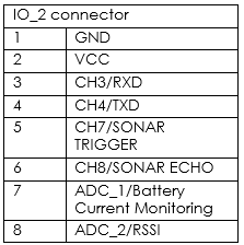
6. IO_2 connector: Serial RX/PWM RX/GPIO/USART3.
When using a PWM receiver, connect CH3/4/7/8 to PWM RX.
When using a 3.3V serial RX receiver (S.Bus, SUMD/H, etc.), use GND/VCC/CH3 (USART3 RX).
CH3/4/7/8 can be used as general purpose I/O if not for serial/PWM RX.
CH7/8 can be used for a 3.3V sonar sensor when it's not used for PWM RX.
ADC_1/2 can be used to connect the battery current monitoring and RSSI signals (3.3V MAX).
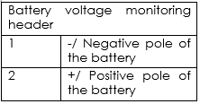
7. Battery voltage monitoring header: To connect the flight controller for battery voltage monitoring and alarm raising.
8. Buzzer header: To connect the buzzer for alarm and information.
A 50mA 5.0V low-power-consumption buzzer is used for the alarm of low voltage and searching for lost aircraft in the Cleanflight software.
9. ESC/Servo output headers: To connect eight motors or servos.
It currently supports PWM ESCs (400Hz by default), Oneshot 125 ESCs and PWM servos (50Hz by default).
10. Boot headers: To recover the firmware.
It runs the STM32 loading program if the soldering pads are bridged; if not, it works normally then.
The back:
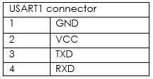
11. USART1 connector: Used for 5.0V I/O ports (OSD, etc.)
DO NOT use it when the USB port is connected.
DO NOT use it when the USART1 headers are in use.
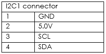
12. I2C1 connector: To connect to external sensors and OLED display. SCL and SDA are the signal ports of the 3.3V.
SF Racing F3 Software Configuration
Debugging the aircraft by setting the software.
1. Do not connect the flight controller to the computer.
2. Pull out all the connecting cables of the flight controller.
3. Add to Chrome the flight controller software CleanFlight (CF) for SF Racing F3:
https://chrome.google.com/webstore/detail/cleanflight-configurator/enacoimjcgeinfnnnpajinjgmkahmfgb
4. Install the latest USB driver software:
http://www.silabs.com/products/mcu/pages/usbtoUSARTbridgevcpdrivers.aSFx
5. Connect the flight controller to the computer with a USB cable.
6. Open the CleanFlight software. If it cannot be recognized automatically, choose the correct COM port of the flight controller.
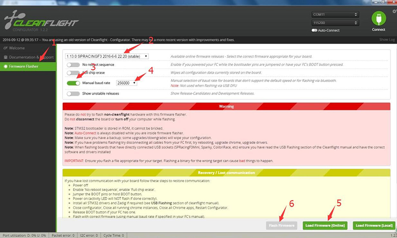
7. Upgrade the firmware
We strongly recommend you to upgrade the firmware of the flight controller immediately to use the latest functions and corrected version. DO NOT fly the aircraft until the firmware has been upgraded.
(1) Click Firmware Flasher
(2) Choose the latest and stable version for the SFRACING F3
(3) Choose Manual baud rate
(4) Set the baud rate as 256000
(5) Click Load Firmware (Online) to load the firmware
(6) Click Flash firmware
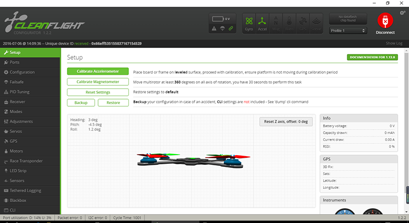
8. Click connect and make sure the communication has been established.
Notes of Soldering:
1. Use a high-quality soldering iron and good melt tin.
2. Cover the pads sufficiently when soldering.
3. Ensure the smoke can be discharged in time.
4. The flight controller is supplied with a bag of straight and right-angled pin headers. Choose carefully when using. You can solder headers to top or the bottom of the board. Once you have soldered pin headers in place, DO NOT attempt to remove them unless you are highly skilled in de-soldering and have the correct tools.
FAQ
Q: The light in the flight controller does not light up.
A: Please check the 5V power supply.
Q: The flight controller keeps beeping.
A: Please check whether the configuration of the receiver data and battery voltage monitoring is correct.
Q: The activity light does not flash.
A: Follow the recovery procedure in the configurator. It’s likely caused by the wrong firmware.
