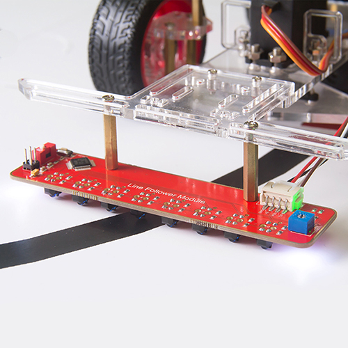
Line Follower Module
Contents
Introduction
The TCRT5000 infrared photoelectric switch adopts a high transmit power infrared photodiode and a highly sensitive phototransistor. It works by applying the principle of objects' reflecting IR light – the light is emitted, then reflected, and sensed by the synchronous circuit. Then it determines whether there exists an object or not by the light intensity. It can easily identify black and white lines.
In other words, the different conduction levels of the phototransistor when it passes over black and white lines can generate different output voltages. Therefore, all we need to do is to collect data by the AD converter on the STM8S105C4 and then send the data to the master control board via I2C communication.
This module is an infrared tracking sensor one that uses a TRT5000 sensor. The blue LED of TRT5000 is the emission tube and after electrified it emits infrared light invisible to human eye. The black part of the sensor is for receiving; the resistance of the resistor inside changes with the infrared light received.
Module application in the line following car robot:
Features
1)Uses the MCU STM8S105C4 as the controller, and the TCRT5000 infrared photoelectric sensor on each of the 8 line-following modules
2)Adopts I2C ports which only occupies 4 pins of the MCU
3)The sensor TRT5000 is highly sensitive with reliable performance
4)With a RESET button on the board for resetting, and positioning holes on the board for easy assembly
5)Supply Voltage: 5V; PCB Dimensions: 124mm x 30mm
Module Test
Step 1. Install the Arduino IDE in your computer. For detailed steps, refer to https://www.sunfounder.com/wiki/index.php?title=Install_Arduino_Software
Step 2. Connect the Arduino Uno board.
Wiring:
- Test board ---- Arduino UNO
- VCC ----- 5V
- GND ----- GND
- SCL ----- A5
- SDA ----- A4
- Test board ---- Arduino UNO
After the circuit is energized, the power indicator LED D0 will brighten.
Step 3. Upload the sketch. Copy the following code to arduino IDE , before clicking the Upload (right arrow button) icon, set the Port and Board under Tools menu.
Test Code
Step 4. Check the value on Serial Monitor. Click the icon ![]() at the right upper corner. Place the test board face down the desk and you'll see the value printed on the window as shown blow:
at the right upper corner. Place the test board face down the desk and you'll see the value printed on the window as shown blow:
Note: When the module is working, it's normal to get heated.
Resources

