Motor Driver Shield
Contents
[hide]Introduction
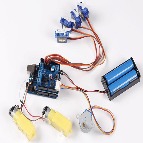
This is an extension shield that can drive 4 servos, 2 DC motors and one stepper motor. All you need to do is plug the shield into the Uno or Mega2560 board. It is powered by two sources – when connected to a control board, it’s powered by the output of the board; to drive a large-current motor, you can connect an external supply for the Motor Driver Shield and the control board. There's an indicator LED on the shield. When it's not in use, you can power the shield off by the switch and it won't influence the use of the control board. The working voltage is 6.5V-12V.
Schematic Diagram
Power Supply
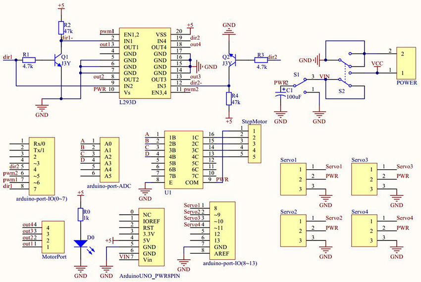
This shield is a dual-supply one. It can be connected directly to the Uno or Mega2560 board which then serves as the supply. But if you want to drive a DC motor of 5V or higher, you need an external power then. S1 is a single-pole double-throw (SPDT) switch and controls the power of the shield. Pull it to OFF and the whole shield will not work. S2 is a 6-pin self-lock button switch that controls the external power supply. When you press down the button, the external power source is connected to shield and will also supply the control board. Thus, the external power can be no higher than 12V.
When the Motor Driver Shield is not in use, just pull S1 to OFF. And the shield will not affect the control board.
Connecting DC Motor
L293D
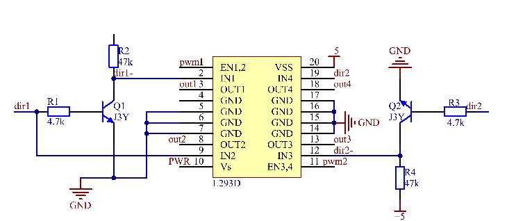
The two DC motors connected are controlled by the L293D chip.
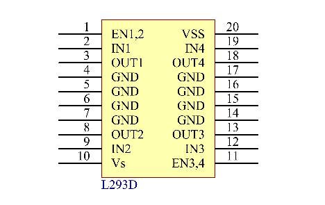
The L293D is a 4-channel monolithic integrated motor driver chip of high voltage and high current. L293D has two pins (Vs and VSS) for power supply. Vs is used to supply power for the motor, while VSS, for the chip. If a small DC motor is used, connect both pins to +5V. If you use a higher power motor, you need to connect Vs to an external power supply.
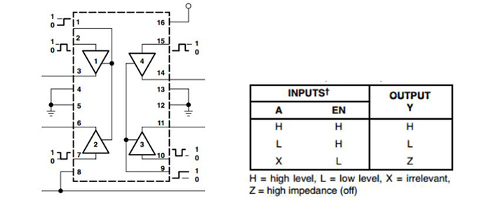
See the schematic diagram of the L293D chip below. EN is an enable pin – active when high level is received. A represents inputs, and Y, output. The relationship between the two pins are shown in the table below. When EN is High, if A is High, Y output is High; if A is Low, Y is Low too. When EN is Low, the L293D does not work.
Pricinple
Pin EN1,2 and EN3,4 are controlled by the pin pwm1 (pin 5 of the control board) and pwm2 (pin 6 of control board), when IN1 and IN2, by dir1 (pin 7 of the control board). When EN1,2 is High, if IN2 is also High, the transistor is energized, thus making IN1 Low and the motors connected to out1 and out2 start spinning; if IN2 is Low, by default IN1 is High, so the motors will rotate in the opposite direction.
IN3 and IN4 are controlled by dir2 (pin4 of the control board). When EN3,4 is High, if IN4 is High too, the transistor is energized, thus making IN3 Low and the motors connected to out3 and out4 start spinning; if IN4 is Low, by default IN3 is High, so the motors will rotate in the opposite direction.
Test Code
/****************************************************
* Name: DC Motor
* Function: the motor rotate clockwise 1s and rotate counterclockwise 1s
*****************************************************/
//Email:support@sunfounder.com
//Website:www.sunfounder.com
#define PWM1 6 //pwm1 connects to pin6
#define PWM2 5 //pwm2 connects to pin5
#define DIR1 7 //dir1 connects to pin7
#define DIR2 4 //dir2 connects to pin4
void setup()
{
  //set all the pin as OUTPUT
  pinMode(PWM1, OUTPUT);
  pinMode(PWM2, OUTPUT);
  pinMode(DIR1, OUTPUT);
  pinMode(DIR2, OUTPUT);
}
void loop() {
  //1 represent the motor connect to out1 and out2
  ctlDCMotor(1, 255);
  ctlDCMotor(2, 255);
  delay(1000);//delay 1s
  ctlDCMotor(1, -255);
  ctlDCMotor(2, -255);
  delay(1000);//delay 1s
}
//set the motors rotate direction
void ctlDCMotor(byte MotorID, int speeds)
{
 //motor1 rotate
 if (MotorID == 1)
 {
   if (speeds > 0)
   {
     digitalWrite(DIR1, HIGH);
   }
   else
   {
     digitalWrite(DIR1, LOW);
   }
   if (abs(speeds) > 255)
   {
     speeds = 255;
   }
   analogWrite(PWM1, abs(speeds));
   //Serial.print("...........................................................left:");
   //Serial.println(abs(speeds));
 }
 //motor2 rotate
 else if (MotorID == 2)
 {
   if (speeds > 0)
   {
     digitalWrite(DIR2, HIGH);
   }
   else
   {
     digitalWrite(DIR2, LOW);
   }
   if (abs(speeds) > 255)
   {
     speeds = 255;
   }
   analogWrite(PWM2, abs(speeds));
   //Serial.print("...........................................................right:");
   //Serial.println(abs(speeds));
 }
}
