4-Channel High Level Trigger Relay
Contents
[hide]Introduction
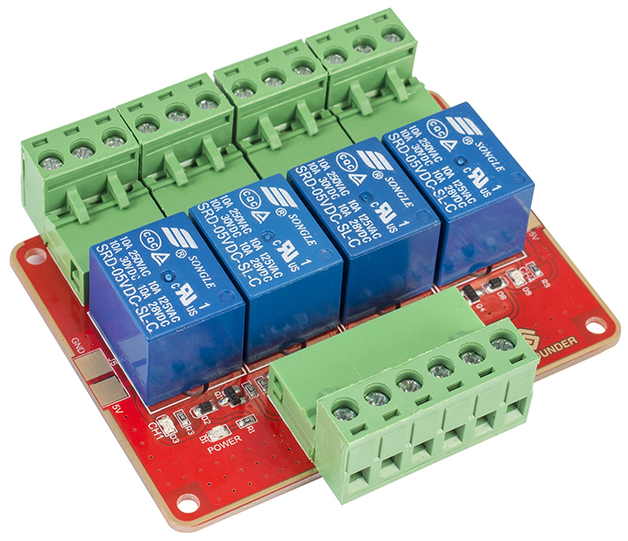
This is a 4-channel HIGH level trigger relay, applicable to Arduino and Raspberry Pi, Relays are suitable for driving high power electronic devices such as lights, electric fans and air conditions, There are two soldering points for 5V and GND at the two ends of the module. So you can just weld other relay modules to it and have a relay module of more channels, signals of which are independent of each other. You can just unplug the headers to disconnect the device with the module after the experiment and don't need to unscrew the wires in the socket. Kindly reminder: Be careful with your fingers when unplugging the headers.

Sending a HIGH level to SIG; the NPN transistor is energized and the coil of the relay is electrified. Thus, the normally open contact of the relay is closed, while the normally closed contact of the relay will be open. Send a LOW level to SIG; the transistor will be de-energized and the relay will restore to the initial state.
The schematic of the relay module is shown as following:
4_channel_HIGH_Relay_Schematic![]()
Features
1) Support control of 10A 30V DC and 10A 250V AC signals 2) 5V 4-Channel Relay interface board, and each one needs 15-20mA Driver Current 3) HIGH level trigger, with indicator LEDs showing working status 4) With two soldering points for 5V and GND, the module can be extended to 6- or 8-channel relay one with other relay modules 5) Working voltage: 5V; PCB size: 5.6 x 7.5 cm ->2.20 inch x 2.95 inch
Principle of relay
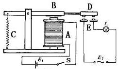
See the picture here: A is an electromagnet, B armature, C spring, D moving contact, and E fixed contacts. There are two fixed contacts, a normally closed and a normally open. When the coil is not energized, the normally open contact is the one that is off, while the normally closed one is the other that is on.
Add a certain voltage to the coil and some currents will pass through the coil thus generating the electromagnetic effect. So the armature overcomes the tension of the spring and is attracted to the core, thus closing the moving contact of the armature and the normally open contact (or you may say releasing the former and the normally closed contact). After the coil is de-energized, the electromagnetic force disappears and the armature moves back to the original position, releasing the moving contact and normally closed contact. The closing and releasing of the contacts results in power on and off of the circuit.
Testing Experiment
Experiment Principle
When a low level is supplied to signal terminal of the 4-channel relay, the LED at the output terminal will light up. Otherwise, it will turn off. If a periodic high and low level is supplied to the signal terminal, you can see the LED will cycle between on and off.
For Arduino
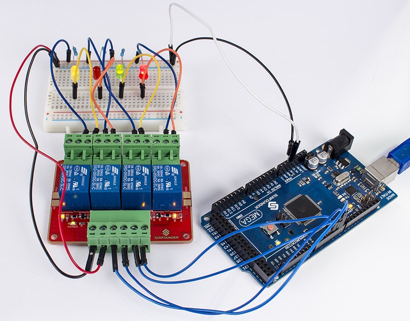
Step 1:Connect the signal terminal CH1、CH2、CH3、CH4of 4-channel relay to digital port 3、4、5、6 of the SunFounder Mega2560 board, and connect an LED at the output terminal.
| 4-channel relay | Mega2560 |
| CH1 | 3 |
| CH2 | 4 |
| CH3 | 5 |
| CH4 | 6 |
Step 2: Copy the code to your IDE and then upload to the board
/***************************************************************************
 * Filename: 4_channel_HIGH_Relay
 * Description: A simple code to control the 4 channel Relay ON or OFF
 * Author: Daisy
 * E-mail: service@sunfounder.com
 * Website: www.sunfounder.com
 * Update: Daisy  2016-9-14  Add comments
 **************************************************************************/

//the relays connect to
int IN1 = 3;
int IN2 = 4;
int IN3 = 5;
int IN4 = 6;
#define ON   0    //assign 0 to ON
#define OFF  1    //assign 1 to OFF
void setup()
{
  relay_init();//initialize the relay
}

void loop() {

  relay_SetStatus(ON, OFF, OFF,OFF);//turn on RELAY_1
  delay(2000);//delay 2s
  relay_SetStatus(OFF, ON, OFF,OFF);//turn on RELAY_2
  delay(2000);//delay 2s
  relay_SetStatus(OFF, OFF, ON,OFF);//turn on RELAY_3
  delay(2000);//delay 2s
  relay_SetStatus(OFF, OFF, OFF,ON);//turn on RELAY_3
  delay(2000);//delay 2s
}
void relay_init(void)//initialize the relay
{
  //set all the relays OUTPUT
  pinMode(IN1, OUTPUT);
  pinMode(IN2, OUTPUT);
  pinMode(IN3, OUTPUT);
  pinMode(IN4, OUTPUT);
  relay_SetStatus(OFF,OFF,OFF,OFF);//turn off all the relay
}
//set the status of relays
void relay_SetStatus( unsigned char status_1,  unsigned char status_2, unsigned char status_3,unsigned char status_4)
{
  digitalWrite(IN1, status_1);
  digitalWrite(IN2, status_2);
  digitalWrite(IN3, status_3);
  digitalWrite(IN4, status_4);

}
The actual figure is shown below:
For raspberry pi
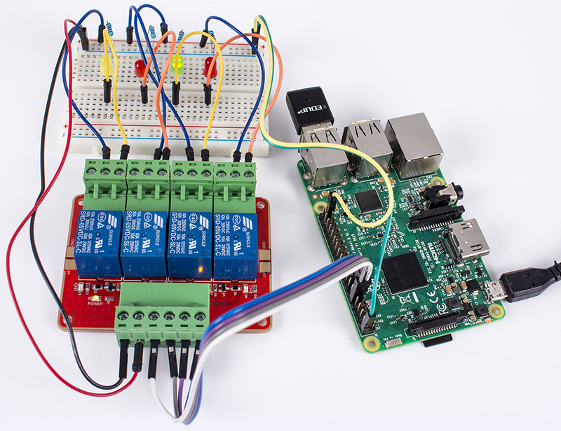
Step1: Connect the signal terminal CH1、CH2、CH3、CH4 of 4-channel relay to port 17、18、27、22 of the Raspberry Pi, and connect an LED at the output terminal.
| 4-channel relay | Raspberry Pi |
| CH1 | 17 |
| CH2 | 18 |
| CH3 | 27 |
| CH4 | 22 |
Step 2: Copy the code and then run the code
#!/usr/bin/env python
'''
**********************************************************************
* Filename 		: 4_channel_relay.py
* Description 	: a sample script for 4-Channel High trigger Relay
* Author 		: Cavon
* E-mail 		: service@sunfounder.com
* Website 		: www.sunfounder.com
* Update 		: Cavon    2016-08-04
* Detail		: New file
**********************************************************************
'''
import RPi.GPIO as GPIO
from time import sleep

Relay_channel = [17, 18, 27, 22]

def setup():
	GPIO.setmode(GPIO.BOARD)
	GPIO.setup(Relay_channel, GPIO.OUT, initial=GPIO.LOW)
	print "|=====================================================|"
	print "|         4-Channel High trigger Relay Sample         |"
	print "|-----------------------------------------------------|"
	print "|                                                     |"
	print "|          Turn 4 channels on off in orders           |"
	print "|                                                     |"
	print "|                    17 ===> CH1                      |"
	print "|                    18 ===> CH2                      |"
	print "|                    27 ===> CH3                      |"
	print "|                    22 ===> CH4                      |"
	print "|                                                     |"
	print "|                                           SunFounder|"
	print "|=====================================================|"

def main():
	while True:
		for i in range(0, len(Relay_channel)):
			print '...Relay channel %d on' % i+1
			GPIO.output(Relay_channel[i], GPIO.HIGH)
			sleep(0.5)
			print '...Relay channel %d off' % i+1
			GPIO.output(Relay_channel[i], GPIO.LOW)
			sleep(0.5)

def destroy():
	GPIO.output(Relay_channel, GPIO.LOW)
	GPIO.cleanup()

if __name__ == '__main__':
	setup()
	try:
		main()
	except KeyboardInterrupt:
		destroy()
The actual figure is shown below:


