Difference between revisions of "Flame sensor Module"
(→Introduction) |
(→Flame sensor in the experiment----Experimental Procedures) |
||
| Line 34: | Line 34: | ||
The wiring between the passive buzzer and SunFounder Uno board:<br> | The wiring between the passive buzzer and SunFounder Uno board:<br> | ||
[[File:Flame sensor4.png]] | [[File:Flame sensor4.png]] | ||
| − | [[File:Flame sensor5.png]] | + | [[File:Flame sensor5.png]]<br> |
Step 2: Program (Please refer to the example code in LEARN -> Get Tutorial on our website) | Step 2: Program (Please refer to the example code in LEARN -> Get Tutorial on our website) | ||
Step 3: Compile | Step 3: Compile | ||
Revision as of 04:29, 23 March 2016
Contents
[hide]Introduction
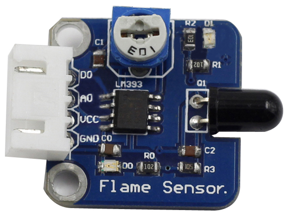
A flame sensor module that consists of a flame sensor, resistor, capacitor, potentiometer, and comparator LM393 in an integrated circuit. It can detect infrared light with a wavelength ranging from 700nm to 1000nm.The far-infrared flame probe converts the strength changes of the external infrared light into current changes.
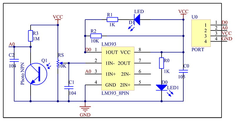
The schematic diagram of the module is as follows:
Features
1) Equipped with power light and a signal output indicator
2) Support a detection angle of appr. 60 degrees; particularly sensitive to flame spectrum.
3) Contain an adjustable precision potentiometer for sensitivity adjustment .
4) With a comparator LM393 to output both digital and analog signals at the same time
5) Connected directly with I/O port of MCU, needless of external circuit
6) Sensitive to flame, also responsive to general light; generally used for flame
7) Detect flame or light of a wavelength ranging from 760 to 1100 nm.
8) Output clean signals by a comparator, with good waveform and driving capability as strong as more than 15mA
9) Working voltage: 3.3V - 5V; PCB size: 2.3 x 2.3 cm
Application
It is applicable to all kinds of flame and can be used for fire detection (e.g. flame alarm).
Flame sensor in the experiment----Components
- 1 * SunFounder Uno board
- 1 * USB data cable
- 1 * Flame sensor module
- 1 * Passive buzzer module
- 1 * 4-Pin anti-reverse cable
- 1 * 3-Pin anti-reverse cable
Flame sensor in the experiment----Experimental Principle
There are several types of flame sensors. In this experiment, we will use a far-infrared flame sensor. It can detect infrared light with a wavelength ranging from 700nm to 1000nm. A far-infrared flame probe converts the strength changes of the external infrared light into current changes. And then it converts analog quantities into digital ones.
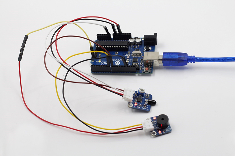
In this experiment, connect pin D0 to the digital port 8 of the SunFounder board. Then when the flame sensor detects flame signals, the buzzer beeps and the corresponding LED lights up. When it detects no flame signals, the buzzer stops and the LED goes out.
Flame sensor in the experiment----Experimental Procedures
Step 1: Build the circuit
The wiring between the flame sensor and SunFounder Uno board:
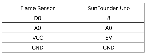
The wiring between the passive buzzer and SunFounder Uno board:

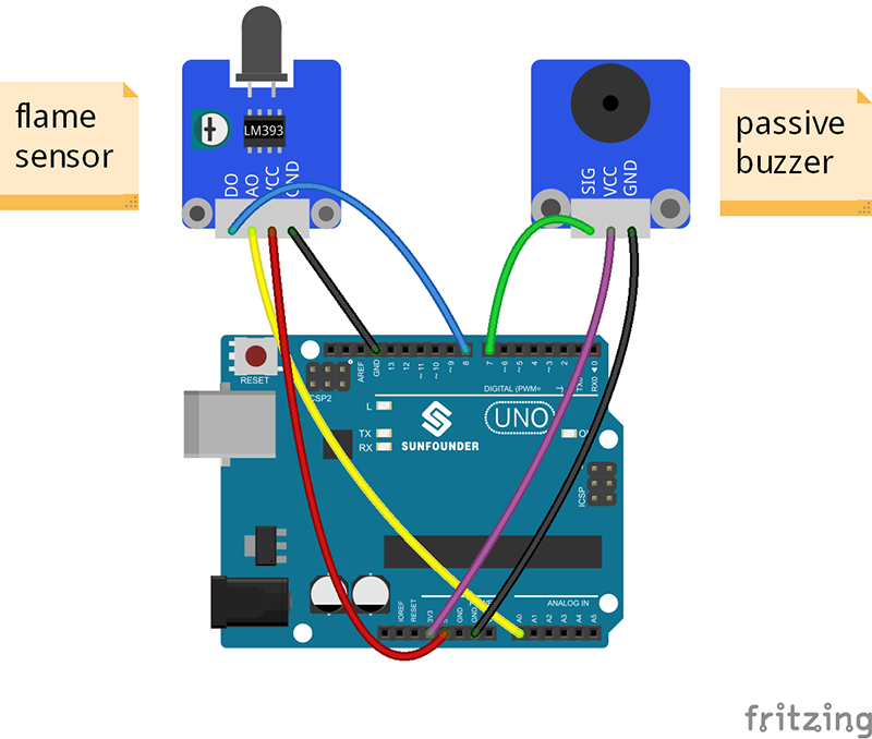
Step 2: Program (Please refer to the example code in LEARN -> Get Tutorial on our website)
Step 3: Compile
Step 4: Upload the sketch to SunFounder Uno board
Now, ignite a lighter near the flame sensor. Then the buzzer will beep, and the LED on the flame sensor module and that attached to pin 13 of the SunFounder board will light up.
