Difference between revisions of "Esp8266 Wifi Module"
| Line 1: | Line 1: | ||
| − | = | + | =Introduction'= |
[[File:Esp8266 and pin .png]]<br> | [[File:Esp8266 and pin .png]]<br> | ||
ESP8266 is an UART-WiFi transparent transmission module with ultralow power consumption, specially designed for the needs of a new connected world. It offers a complete and self-contained Wi-Fi networking solution, allowing it to either host the application or to offload all Wi-Fi networking functions from another application processor.<br> | ESP8266 is an UART-WiFi transparent transmission module with ultralow power consumption, specially designed for the needs of a new connected world. It offers a complete and self-contained Wi-Fi networking solution, allowing it to either host the application or to offload all Wi-Fi networking functions from another application processor.<br> | ||
ESP8266 has powerful on-board processing and storage capabilities that allow it to be integrated with the sensors and other application specific devices through its GPIOs with minimal development up-front and minimal loading during runtime. Its high degree of on-chip integration allows for minimal external circuitry, and the entire solution, including front-end module, is designed to occupy minimal PCB area. ESP8266 Serial Wifi Wireless Transceiver Module is suitable for Uno, Mega 2560 and Nano.<br> | ESP8266 has powerful on-board processing and storage capabilities that allow it to be integrated with the sensors and other application specific devices through its GPIOs with minimal development up-front and minimal loading during runtime. Its high degree of on-chip integration allows for minimal external circuitry, and the entire solution, including front-end module, is designed to occupy minimal PCB area. ESP8266 Serial Wifi Wireless Transceiver Module is suitable for Uno, Mega 2560 and Nano.<br> | ||
| − | = | + | =Pin Functions= |
<center> | <center> | ||
{| border="1" class="wikitable" | {| border="1" class="wikitable" | ||
| Line 23: | Line 23: | ||
|3 | |3 | ||
|CU_PD | |CU_PD | ||
| − | | | + | |1) Working at high level;<br> |
| − | + | 2) Power off when low level is supplied <br> | |
|- | |- | ||
|4 | |4 | ||
|GPIO2 | |GPIO2 | ||
| − | | | + | |1) It should be high level when power on, hardware pull-down is not allowed;<br> |
2)Pull-up by default; | 2)Pull-up by default; | ||
|- | |- | ||
| Line 37: | Line 37: | ||
|6 | |6 | ||
|GPIO0 | |GPIO0 | ||
| − | | | + | |1) WiFi Status indicator; <br> |
| − | + | 2) Operation mode selection:<br> | |
Pull-up: Flash Boot, operation mode <br> | Pull-up: Flash Boot, operation mode <br> | ||
Pull-down: UART Download, download mode | Pull-down: UART Download, download mode | ||
| Line 48: | Line 48: | ||
|8 | |8 | ||
|RXD | |RXD | ||
| − | | | + | |1) UART_RXD,Receiving<br> |
| − | + | 2) General Purpose Input/Output: GPIO3; | |
|} | |} | ||
</center> | </center> | ||
| − | = | + | =Schematic= |
<center> | <center> | ||
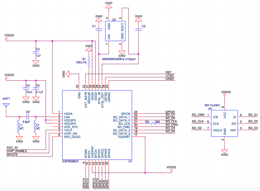
[[File:Esp8266 schematic.png]] | [[File:Esp8266 schematic.png]] | ||
</center> | </center> | ||
| − | = | + | =Features= |
• 802.11 b/g/n<br> | • 802.11 b/g/n<br> | ||
• Integrated low power 32-bit MCU<br> | • Integrated low power 32-bit MCU<br> | ||
| Line 75: | Line 75: | ||
• Operating temperature range -40C ~ 125C<br> | • Operating temperature range -40C ~ 125C<br> | ||
• FCC, CE, TELEC, Wi-Fi Alliance, and SRRC certified<br> | • FCC, CE, TELEC, Wi-Fi Alliance, and SRRC certified<br> | ||
| − | = | + | =How to Test and Debug Esp8266= |
| − | == | + | =='''Use AT Command'''== |
'''Preparation''' | '''Preparation''' | ||
Revision as of 07:50, 5 June 2017
Contents
[hide]Introduction'

ESP8266 is an UART-WiFi transparent transmission module with ultralow power consumption, specially designed for the needs of a new connected world. It offers a complete and self-contained Wi-Fi networking solution, allowing it to either host the application or to offload all Wi-Fi networking functions from another application processor.
ESP8266 has powerful on-board processing and storage capabilities that allow it to be integrated with the sensors and other application specific devices through its GPIOs with minimal development up-front and minimal loading during runtime. Its high degree of on-chip integration allows for minimal external circuitry, and the entire solution, including front-end module, is designed to occupy minimal PCB area. ESP8266 Serial Wifi Wireless Transceiver Module is suitable for Uno, Mega 2560 and Nano.
Pin Functions
| Pin | Name | Description |
|---|---|---|
| 1 | TXD | 1) UART_TXD,sending; 2) General Purpose Input/Output:GPIO1; |
| 2 | GND | GND |
| 3 | CU_PD | 1) Working at high level; 2) Power off when low level is supplied |
| 4 | GPIO2 | 1) It should be high level when power on, hardware pull-down is not allowed; 2)Pull-up by default; |
| 5 | GPIO16 | External Reset signal, reset when low level is supplied; work when high level is supplied (high level by default); |
| 6 | GPIO0 | 1) WiFi Status indicator; 2) Operation mode selection: |
| 7 | VCC | Power Supply(3.3V) |
| 8 | RXD | 1) UART_RXD,Receiving 2) General Purpose Input/Output: GPIO3; |
Schematic
Features
• 802.11 b/g/n
• Integrated low power 32-bit MCU
• Integrated 10-bit ADC
• Integrated TCP/IP protocol stack
• Integrated TR switch, balun, LNA, power amplifier and matching network
• Integrated PLL, regulators, and power management units
• Supports antenna diversity
• Wi-Fi 2.4 GHz, support WPA/WPA2
• Support STA/AP/STA+AP operation modes
• Support Smart Link Function for both Android and iOS devices
• SDIO 2.0, (H) SPI, UART, I2C, I2S, IR Remote Control, PWM, GPIO
• A-MPDU & A-MSDU aggregation & 0.4s guard interval
• Deep sleep power <10uA, Power down leakage current < 5uA
• Wake up and transmit packets in < 2ms
• Standby power consumption of < 1.0mW (DTIM3)
• +20 dBm output power in 802.11b mode
• Operating temperature range -40C ~ 125C
• FCC, CE, TELEC, Wi-Fi Alliance, and SRRC certified
How to Test and Debug Esp8266
Use AT Command
Preparation
-1 * PL2303HXD
-1 * SunFounder Uno Board
-1 * ESP8266
Procedures
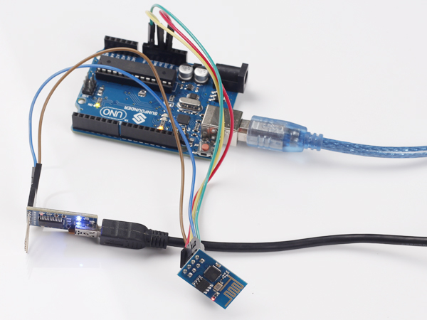
Step 1: wire
Connect UTXD of ESP8266 to RXD of PL2303, URXD to TXD, CH_PD to 5v(recommend 3.3v), GND to GND, and VCC to 3.3v. The Uno board here is used to supply 3.3v power. PL2303 is a USB to Serial Bridge Controller. You can also use other components, such as FTDI.
Step 2:set parameters
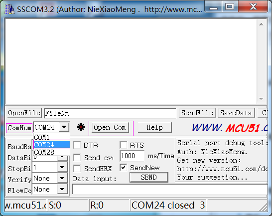
After wiring, open the serial port debug tool sscom32. Set parameters at first.
1) Open the serial port, click Open Com. Select the correct port, as shown below.
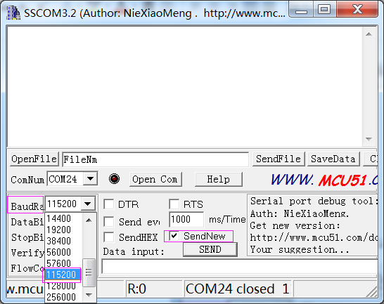
2) Select the correct baud rate. Here select 115200 bps. Click SendNew, as shown below.
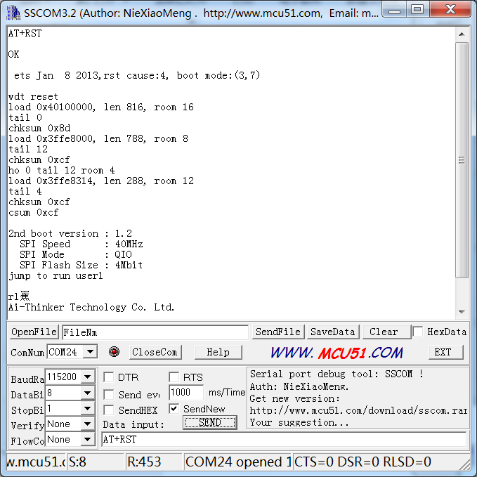
Step3:AT instructions Now, you can start to send instructions. Enter "AT+RST" in the text box. It’s used to restart the module. If ESP8266 goes well, OK will be sent, as shown below:
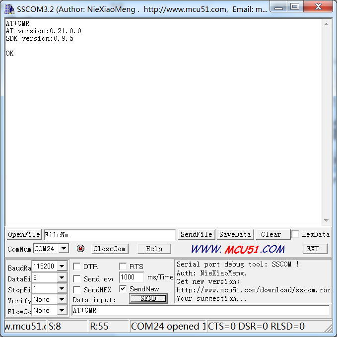
You can also send other instructions, such as "AT+GMR". It is used to check the version of AT commands and SDK that you are using, the type of which is "executed".
For more information about ESP8266 AT Instructions. please refer to ESP8266EX_AT_Instruction_Set.pdf.
Resource
ESP8266EX_AT_Instruction_Set![]()
ESP8266_Module_User_Guide![]()
Sscom32E![]()
