Difference between revisions of "3DR Radio Telemetry Module"
(Created page with "==Introduction== <center>File:3DR01.png<center><br><br> The 3DR Radio telemetry system is designed as an open source Xbee replacement radio set, offering a lower price, lo...") |
(→Introduction) |
||
| Line 1: | Line 1: | ||
==Introduction== | ==Introduction== | ||
| − | <center>[[File:3DR01.png]]<center><br><br> | + | <center>[[File:3DR01.png]]</center><br><br> |
The 3DR Radio telemetry system is designed as an open source Xbee replacement radio set, offering a lower price, longer range and superior performance to Xbee radios. It’s available in 433Mhz and in the following configurations: serial board (for the air) and USB (for the ground).<br> | The 3DR Radio telemetry system is designed as an open source Xbee replacement radio set, offering a lower price, longer range and superior performance to Xbee radios. It’s available in 433Mhz and in the following configurations: serial board (for the air) and USB (for the ground).<br> | ||
Air Radio Module is used for UAV or equipment or aerial work equipment. Ground Radio Module is used to connect to a computer or display images on other equipment in the ground. When two modules are bound with the wireless signal, we can use the APM ground station (Mission Planner) to adjust and upgrade the parameters.<br> | Air Radio Module is used for UAV or equipment or aerial work equipment. Ground Radio Module is used to connect to a computer or display images on other equipment in the ground. When two modules are bound with the wireless signal, we can use the APM ground station (Mission Planner) to adjust and upgrade the parameters.<br> | ||
| − | Now, let's use Mission Planner to test the Radio Telemetry Module.<br> | + | Now, let's use Mission Planner to test the Radio Telemetry Module.<br> |
| + | |||
==Features== | ==Features== | ||
* 915 MHz frequency band. Receiver sensitivity to -117 dBm<br> | * 915 MHz frequency band. Receiver sensitivity to -117 dBm<br> | ||
Revision as of 05:49, 14 March 2017
Introduction
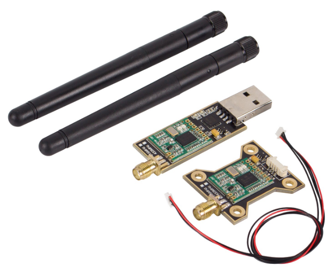
The 3DR Radio telemetry system is designed as an open source Xbee replacement radio set, offering a lower price, longer range and superior performance to Xbee radios. It’s available in 433Mhz and in the following configurations: serial board (for the air) and USB (for the ground).
Air Radio Module is used for UAV or equipment or aerial work equipment. Ground Radio Module is used to connect to a computer or display images on other equipment in the ground. When two modules are bound with the wireless signal, we can use the APM ground station (Mission Planner) to adjust and upgrade the parameters.
Now, let's use Mission Planner to test the Radio Telemetry Module.
Features
- 915 MHz frequency band. Receiver sensitivity to -117 dBm
- Small and lightweight, it can be placed in the sleeving and also be tied to the mechanical arm.
- 2.5 dBi antenna, the scope of transmitting and receiving up to 1000meters.
- Transmit power up to 20dBm (100mW). Transparent serial link. Antenna connectors: RP-SMA connector.
- MAVLink protocol framing and status reporting.
Testing Procedures
Components Needed
1 x Adjustable regulated DC power supply
1 x Standard Radio Module G
1 x Radio Module A
1 x APM flight controller
A computer with Mission Planner installed
Notes: Check whether there is a short circuit between the power supply of the test board and the ground (E.g. VCC and GND).
Step 1.' Schematic diagram:
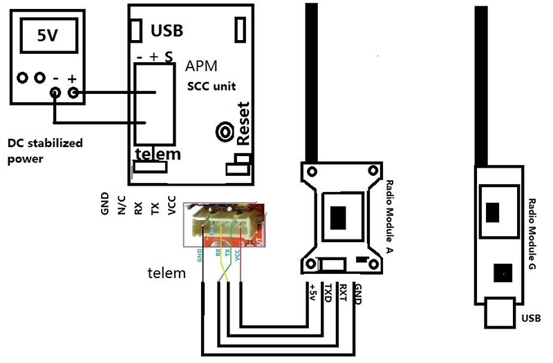
Step 2. Connect the Radio Module G to the computer by USB, then install the FTDI driver (you can use Driver Genius or other tools to download it). Find the correct port on Device Manager.
Step 3. Connect the Radio Module A according to the schematic diagram, and provide the DC power with 5V, and you will see the green light on the two radio telemetry modules blink for a while and then keep brighten constantly, which indicates the two modules have been matched successfully.
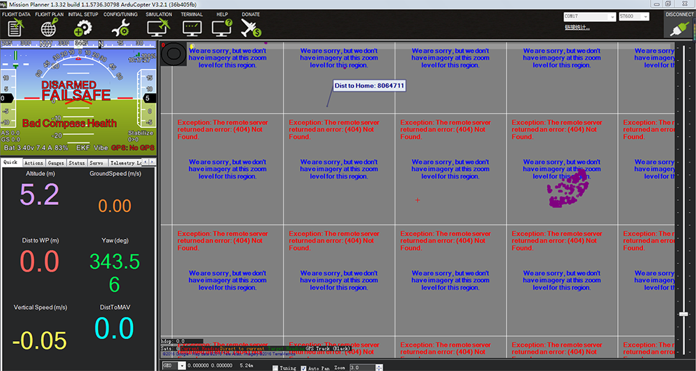
Step 4. Open the Mission Planner and you will see the interface below:
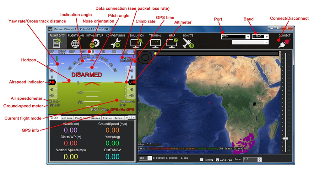
Choose the correct port and select 57600 as the baud rate, click Connect
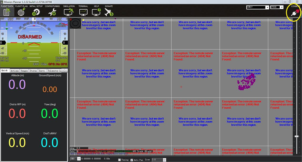
If the two modules have been connected correctly, the red light in the module will blink and the Connect icon will change from red to green.

Wait till the Mission Planner receives the data from the APM flight controller. Move the board and you will see the parameter change in the area below, which indicates the communication between the radio telemetry modules is good.
Note:
There are two status indicators in the module, one in red and the other in green. See their meanings below:
Green LED blinks - Looking for another radio telemetry module.
Green LED constantly lights up - Connected successfully with another radio telemetry module.
Red LED blinks - Data transmission.