Difference between revisions of "2 Channel 5V Relay Module"
| Line 1: | Line 1: | ||
=='''Introduction'''== | =='''Introduction'''== | ||
| − | [[File:2cha1.jpg]] | + | [[File:2cha1.jpg]]<br> |
This is a LOW Level 5V 2-channel relay interface board, and each channel needs a 15-20mA driver current. It can be used to control various appliances and equipment with large current. It is equiped with high-current relays that work under AC250V 10A or DC30V 10A. It has a standard interface that can be controlled directly by microcontroller. | This is a LOW Level 5V 2-channel relay interface board, and each channel needs a 15-20mA driver current. It can be used to control various appliances and equipment with large current. It is equiped with high-current relays that work under AC250V 10A or DC30V 10A. It has a standard interface that can be controlled directly by microcontroller. | ||
Revision as of 06:39, 26 September 2016
Contents
[hide]Introduction
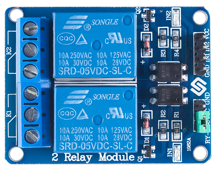
This is a LOW Level 5V 2-channel relay interface board, and each channel needs a 15-20mA driver current. It can be used to control various appliances and equipment with large current. It is equiped with high-current relays that work under AC250V 10A or DC30V 10A. It has a standard interface that can be controlled directly by microcontroller.
Features
- Relay Maximum output: DC 30V/10A, AC 250V/10A
- 2 Channel Relay Module with Optocoupler LOW Level Triger expansion board, which is compatible with arduino
- Standard interface that can be controlled directly by microcontroller ( 8051, AVR, *PIC, DSP, ARM, ARM, MSP430, TTL logic)
- Relay of high quality loose music relays SPDT. A common terminal, a normally open, one normally closed terminal
- optocoupler isolation, good anti-jamming
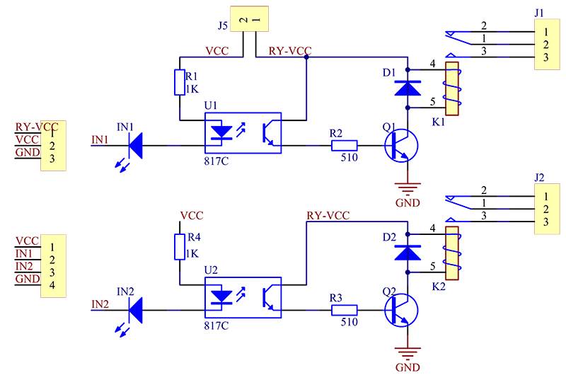
Schematic
VCC and RY-VCC are also the power supply of the relay module. When you need to drive a large power load, you can take the jumper cap off and connect an extra power to RY-VCC to supply the relay; connect VCC to 5V of the MCU board to supply input signals.
principle
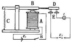
See the picture below: A is an electromagnet, B armature, C spring, D moving contact, and E fixed contacts. There are two fixed contacts, a normally closed one and a normally open one. When the coil is not energized, the normally open contact is the one that is off, while the normally closed one is the other that is on.
Add a certain voltage to the coil and some currents will pass through the coil thus generating the electromagnetic effect. So the armature overcomes the tension of the spring and is attracted to the core, thus closing the moving contact of the armature and the normally open contact (or you may say releasing the former and the normally closed contact). After the coil is de-energized, the electromagnetic force disappears and the armature moves back to the original position, releasing the moving contact and normally closed contact. The closing and releasing of the contacts results in power on and off of the circuit.
Input:
VCC : Connected to positive supply voltage (supply power according to relay voltage)
GND : Connected to negative supply voltage
IN1: Signal triggering terminal 1 of relay module
IN2: Signal triggering terminal 2 of relay module
Output:
Each submodular of the relay has one NC(nomalclose), one NO(nomalopen) and one COM(Common). So there are 2 NC, 2 NO and 2 COM of the channel relay in total. NC stands for the normal close port contact and the state without power; No stands for the normal open port contact and the state with power. COM means the common port. You can choose NC port or NO port according to whether power or not.
Application
General purpose
Testing Experiment
Experiment Principle:
When a low level is supplied to signal terminal of the 2-channel relay, the LED at the output terminal will light up. Otherwise, it will turn off. If a periodic high and low level is supplied to the signal terminal, you can see the LED will cycle between on and off.
For Arduino:
Step 1:
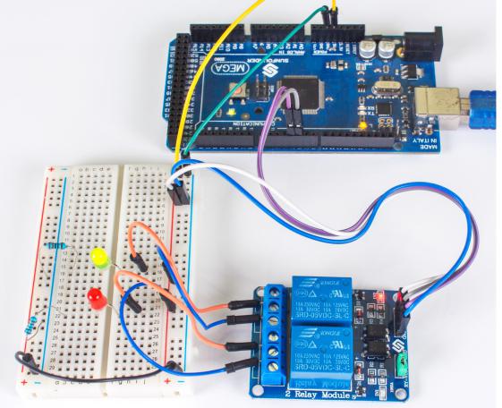
Connect the signal terminal IN1、IN2 of 2-channel relay to digital port 4、5 of the SunFounder Arduino ATMega2560 board, and connect an LED at the output terminal.(Pay attention to that there are only two submodules of the 8-channel relay are used in this example, but you can use the 2 submodules freely.)
- 8-channel relay--------------- Arduino ATMega2560
- IN1------------------------ 4
- IN2------------------------ 5
- 8-channel relay--------------- Arduino ATMega2560
Step 2:
Run the companion procedures text_code of the SunFounder Arduino ATMega2560 board,Please see the source code in Resources at the end of the page.Then you can see the LED cycle between on and off.
The actual figure is shown below:
For raspberry pi
Step1:
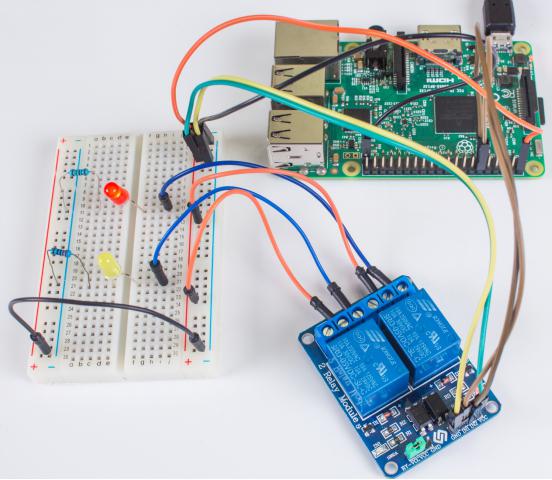
Connect the signal terminal IN2、IN1 of 2-channel relay to port 17、18 of the Raspberry Pi, and connect an LED at the output terminal.
- 2-channel relay------------ Raspberry Pi
- IN2----------------------- 17
- IN1----------------------- 18
- 2-channel relay------------ Raspberry Pi
Step 2:
Run the test_code,Please see the source code in Resources at the end of the page. Then you can see the LED cycle between on and off.
The actual figure is shown below:
Component List
1 x 2 Channel Relay Module
Resources
Code for Arduino ATMega2560:
2_test_code_for_arduino_atmega2560![]()
Code for Raspberry Pi :
