Difference between revisions of "Humiture Sensor Module"
| Line 1: | Line 1: | ||
=='''Introduction'''== | =='''Introduction'''== | ||
| − | [[File:Humiture.jpg]] | + | [[File:Humiture.jpg]]<br> |
The digital temperature and humidity sensor DHT11 is a composite sensor that contains a calibrated digital signal output of temperature and humidity. The technology of a dedicated digital modules collection and the temperature and humidity sensing technology are applied to ensure that the product has high reliability and excellent long-term stability. <br> | The digital temperature and humidity sensor DHT11 is a composite sensor that contains a calibrated digital signal output of temperature and humidity. The technology of a dedicated digital modules collection and the temperature and humidity sensing technology are applied to ensure that the product has high reliability and excellent long-term stability. <br> | ||
The sensor includes a resistive sense of wet component and an NTC temperature measurement device, and is connected with a high-performance 8-bit microcontroller. | The sensor includes a resistive sense of wet component and an NTC temperature measurement device, and is connected with a high-performance 8-bit microcontroller. | ||
The schematic diagram of the Humiture Sensor Module is as shown following:<br> | The schematic diagram of the Humiture Sensor Module is as shown following:<br> | ||
| − | [[File:Hum-sch.png]] | + | [[File:Hum-sch.png]]<br> |
Only three pins are available for use: VCC, GND, and DATA. The communication process begins with the DATA line sending start signals to DHT11, and DHT11 receives the signals and returns an answer signal. Then the host receives the answer signal and begins to receive 40-bit humiture data (8-bit humidity integer + 8-bit humidity decimal + 8-bit temperature integer + 8-bit temperature decimal + 8-bit checksum). <br> | Only three pins are available for use: VCC, GND, and DATA. The communication process begins with the DATA line sending start signals to DHT11, and DHT11 receives the signals and returns an answer signal. Then the host receives the answer signal and begins to receive 40-bit humiture data (8-bit humidity integer + 8-bit humidity decimal + 8-bit temperature integer + 8-bit temperature decimal + 8-bit checksum). <br> | ||
[[File:Dht11.png]] | [[File:Dht11.png]] | ||
Revision as of 10:35, 22 March 2016
Introduction

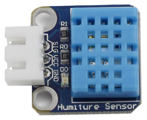
The digital temperature and humidity sensor DHT11 is a composite sensor that contains a calibrated digital signal output of temperature and humidity. The technology of a dedicated digital modules collection and the temperature and humidity sensing technology are applied to ensure that the product has high reliability and excellent long-term stability.
The sensor includes a resistive sense of wet component and an NTC temperature measurement device, and is connected with a high-performance 8-bit microcontroller.
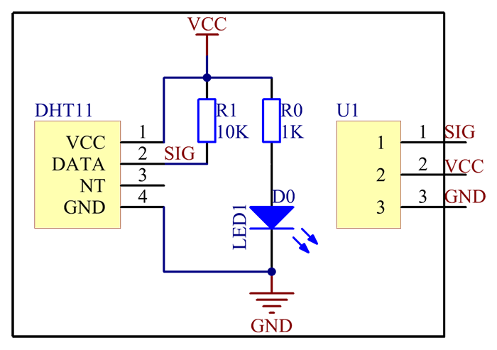
The schematic diagram of the Humiture Sensor Module is as shown following:

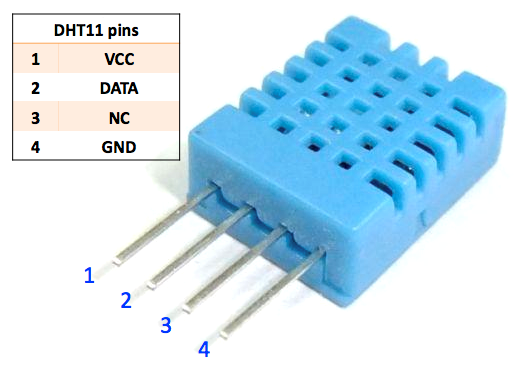
Only three pins are available for use: VCC, GND, and DATA. The communication process begins with the DATA line sending start signals to DHT11, and DHT11 receives the signals and returns an answer signal. Then the host receives the answer signal and begins to receive 40-bit humiture data (8-bit humidity integer + 8-bit humidity decimal + 8-bit temperature integer + 8-bit temperature decimal + 8-bit checksum).

Features
1) A humiture sensor module to test temperature and humidity, which uses the sensor DHT11.
2) Humidity measurement range: 20 - 90%RH
3) Temperature measurement range: 0 - 60℃
4) Output digital signals indicating temperature and humidity
5) Working voltage:DC 5V; PCB size: 2.0 x 2.0 cm
6) Humidity measurement accuracy: ±5%RH
7) Temperature measurement accuracy: ±2℃
Application
The module can be applied to measurement of ambient humidity and temperature