Difference between revisions of "PulseSensor Heart Rate Monitoring Sensor Module"
| Line 27: | Line 27: | ||
='''For Arduino'''= | ='''For Arduino'''= | ||
'''Using Steps'''<br> | '''Using Steps'''<br> | ||
| − | '''Step 1: Connect the circuit.'''<br> | + | =='''Step 1: Connect the circuit.'''==<br> |
[[File:Pulsesensor7.png]]<br> | [[File:Pulsesensor7.png]]<br> | ||
[[File:Pulsesensor6.png]]<br> | [[File:Pulsesensor6.png]]<br> | ||
| − | '''Step 2: Download and add library'''<br> | + | =='''Step 2: Download and add library'''==<br> |
Click here to download the PulseSensorAmped_Arduino_1dot2 library. You should have a zip folder in your Downloads.<br> | Click here to download the PulseSensorAmped_Arduino_1dot2 library. You should have a zip folder in your Downloads.<br> | ||
Open Arduino IDE, then click Sketch -> Include Library -> Add ZIP Library, and select PulseSensorAmped_Arduino_1dot2.zip to include.<br> | Open Arduino IDE, then click Sketch -> Include Library -> Add ZIP Library, and select PulseSensorAmped_Arduino_1dot2.zip to include.<br> | ||
| Line 38: | Line 38: | ||
[[File:Pulsesensor.png]]<br> | [[File:Pulsesensor.png]]<br> | ||
| − | '''Step 3: Flash the code'''<br> | + | =='''Step 3: Flash the code'''==<br> |
Unzip PulseSensorAmped_Arduino_1dot2.zip and open PulseSensorAmped_Arduino_1dot2.ino<br> | Unzip PulseSensorAmped_Arduino_1dot2.zip and open PulseSensorAmped_Arduino_1dot2.ino<br> | ||
[[File:Pulsesensor8.png]]<br> | [[File:Pulsesensor8.png]]<br> | ||
| Line 53: | Line 53: | ||
When the program is successfully loaded, there will display Done uploading. The Arduino program is now successfully downloaded and the Arduino software can be closed. The data will be displayed in Processing.<br> | When the program is successfully loaded, there will display Done uploading. The Arduino program is now successfully downloaded and the Arduino software can be closed. The data will be displayed in Processing.<br> | ||
| − | '''Step 4: Download and use Processing '''<br> | + | =='''Step 4: Download and use Processing '''==<br> |
Click here to download Processing, unzip and install Processing. Download Processing Program folder. There are four files in it. Use Processing to open the code in the red box please.<br> | Click here to download Processing, unzip and install Processing. Download Processing Program folder. There are four files in it. Use Processing to open the code in the red box please.<br> | ||
[[File:Pulsesensor2.png]]<br> | [[File:Pulsesensor2.png]]<br> | ||
Revision as of 06:11, 18 October 2019
Contents
Introduction
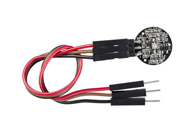
PulseSensor is a reflection type photoelectric analog sensor used to measure pulse and heart rate. Having been worn around the finger or earlobe, the sensor can transmit the collected analog signal to MCU. And then the analog signal will be converted into digital signal. With simple calculation finished, the MCU gets heart rate values and uploads them to computer for drawing the pulse waveform. PulseSensor is an open source hardware, suitable for scientific research and teaching presentation on heart rate subject and secondary development.
Main Features
- Supply Voltage: 3.3V or 5V;
- Output Signal Type: Analog Signal;
- PCB Diameter: 16mm;
- Amplification: 330;
- LED Wavelength: 609nm;
- Output Signal Range: 0~3.3V (3.3V supply voltage) or 0~5V (5V supply voltage);
- 7.Current Range: < 4mA.
Introduction of Pins
- S:Signal Output Wire
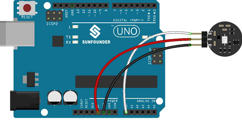
- +:3.3V-5V Working Voltage
- -:Ground
The Principle of the Module
There are three traditional pulse measurement methods: the first one is to extract from ECG signal; the second way is to calculate pulse rate from the fluctuation measured by pressure sensor during blood pressure measurement; the third one is photoelectric volume method. The first two methods of signal extraction will limit the activity of the patient, long-time using will increase the patient's physical and psychological discomfort. As one of the most common methods in monitoring and measuring, photoelectric volume pulse measurement has the characteristics of simple method, convenient to wear and high reliability.
The basic principle of the photoelectric volume method is to take advantage of the different light transmittance of the human body caused by beating blood vessels, and the pulse measurement is carried out by this means. The used sensor is composed of a light source and a photoelectric converter, and is fixed on the finger or the earlobe of a patient through a strap or a clamp. The light source generally employs a light-emitting diode having a certain wavelength (500-700 nm) that is selective for oxygen and hemoglobin in the arterial blood. When the light beam is transmitting through the peripheral blood tube of the human body, the light transmittance of the beam is changed due to the change of the volume of the arterial pulse and the volume of the blood. And the photoelectric transducer receives the light reflected by the human body, converts the light into an electric signal, amplifies and outputs the electric signal. The electric signal change period of the photoelectric converter is the pulse rate because the pulse is a signal that changes periodically with the beating of the heart and the volume of the arterial blood tube is also periodically changed.
According to the relevant literature and experimental results, the wave at the wavelength of 560 nm can reflect the superficial micro-arterial information of the skin, and is suitable for extracting the pulse signal. The sensor uses green LED, model AM2520 with peak wavelength of 515nm.The optical receiver uses APDS-9008, which is an ambient photoreceptor with a peak sensing wavelength of 565nm. the peak wavelengths of the two are similar and the sensitivity is high. In addition, since the frequency band of the pulse signal is generally 0.05~200Hz, the signal range is small (generally at a millivolt level) and susceptible to various signal interference. A low-pass filter and an amplifier composed of the operational amplifier MCP6001 are used at the back of the sensor, the signal is amplified by 331 times, and the DC bias voltage is set to be 1/2 of the power supply voltage by using the voltage dividing resistor, so that the amplified signal can be collected by the AD of the single-chip computer well.
For Arduino
Using Steps
==Step 1: Connect the circuit.==

==Step 2: Download and add library==
Click here to download the PulseSensorAmped_Arduino_1dot2 library. You should have a zip folder in your Downloads.
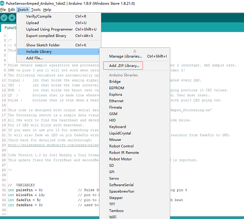
Open Arduino IDE, then click Sketch -> Include Library -> Add ZIP Library, and select PulseSensorAmped_Arduino_1dot2.zip to include.
After including successfully, you can see the example in File -> Examples -> PulseSensorAmped_Arduino_1dot2.
==Step 3: Flash the code==
Unzip PulseSensorAmped_Arduino_1dot2.zip and open PulseSensorAmped_Arduino_1dot2.ino

If you want your sensor to work under the 5V voltage, you don't have to revise the program.
If under the 3.3V, please delete the note followed by the statement in the following picture and recompile your codes. Make sure that your power wire of the sensor is connected to the 3.3V and the AREF of the Arduino board to 3.3V(by default, they are not connected).

We should choose correct board model and serial port number before code download.
Click Tools->Board and choose the Arduino model we use, click Tools->Serial Port, choose Arduino serial port number (can be checked in Device Manager).
Then press the icon Upload, as shown in the following picture.

When the program is successfully loaded, there will display Done uploading. The Arduino program is now successfully downloaded and the Arduino software can be closed. The data will be displayed in Processing.
==Step 4: Download and use Processing ==
Click here to download Processing, unzip and install Processing. Download Processing Program folder. There are four files in it. Use Processing to open the code in the red box please.

Now, we can first click Run then the display page of Processing will appear and we don’t have to check it. The COM port recognized by the software will appear below the original program.
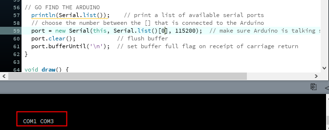
If the software recognizes only one COM port, then serial.list () [0] is the first serial port represented. If multiple serial ports, such as "COM1, COM3", are identified, serial.list () [0] represents COM1, and serial.list () [1] stands for COM3. At this time, fill in the serial number according to the serial port of the board you use.
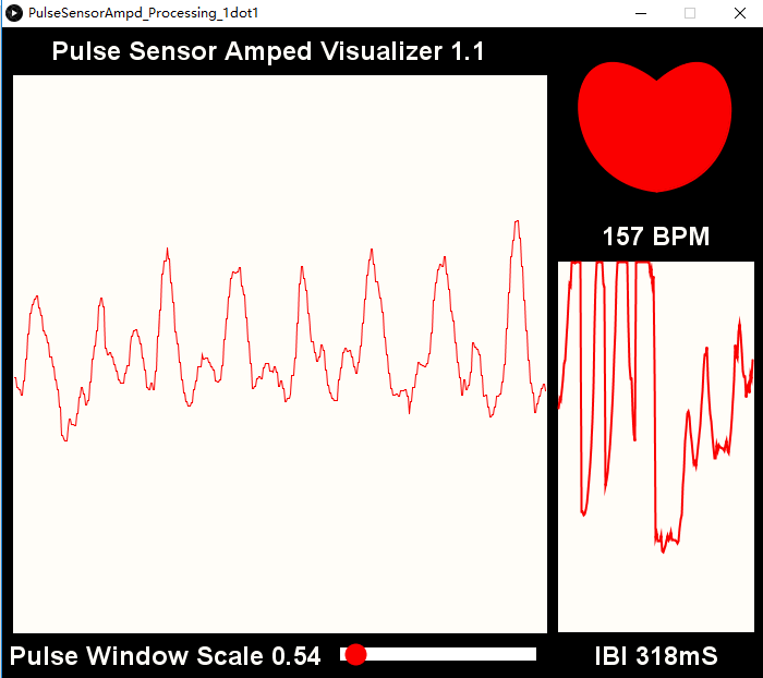
When the serial port sequence is correct, click the run button, put the sensor at the finger or earlobe, and you can see the pulse waveform in the figure below.
On the left is the pulse waveform. BPM:beats per minute. IBI: time between heartbeat in mS.
