Difference between revisions of "Flame Sensor Module"
(→Experimental Procedures For Arduino) |
(→Experimental Procedures For Arduino) |
||
| Line 74: | Line 74: | ||
</pre> | </pre> | ||
| + | [[File:Flame Sensor Module(serial).jpeg]]<br> | ||
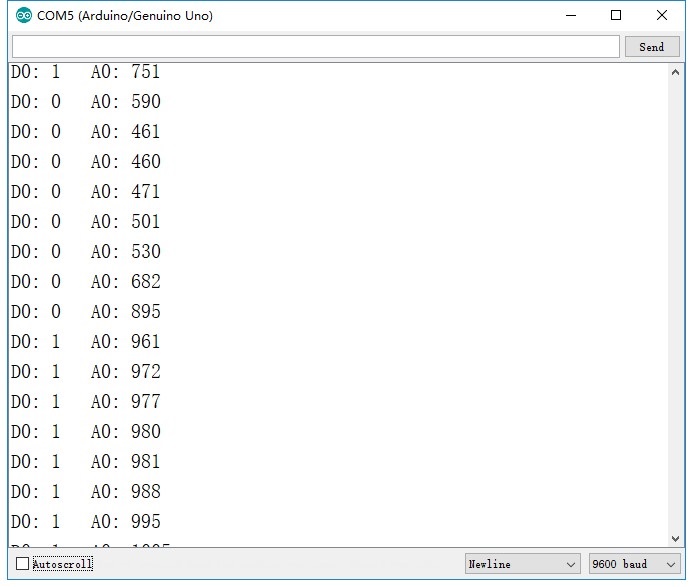
| + | When flame or strong light is detected, the analog value will decrease and the module will output low level. Meanwhile, the indicator light D0-LED will light up.<br> | ||
| + | Notice: The working temperature of the far infrared flame sensor is -25°~85°, and the storage temperature is 30°~100°. So the detector of the sensor can easily get broken down when working under the temperature above the range. So please do not let your detector be too close to the heat source. | ||
Revision as of 08:56, 11 September 2019
Contents
[hide]Introduction

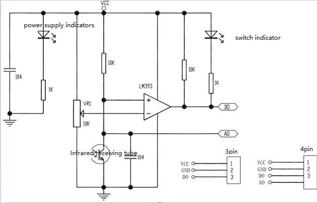
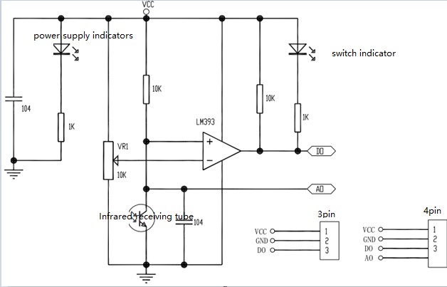
Infrared Flame Sensor is used to detect the ignition sources and the intensity of light for robots. Yet, this product is more sensitive to ignition sources.
Features
- The module can detect flame or light source whose wavelength ranges from 760nm to 1100nm. The detection distance of the flame of lighter is 80 cm. The larger the flame intensity, the farther the test distance is.
- Detection Angle: about 60 degrees.
- The module is sensitive to the flame spectrum.
- Adjustable sensitivity (adjust by using the blue potentiometer).
- Comparator output, clean signal, regular waveform, strong driving ability, current more than 15mA.
- Working Voltage: 3.3V~5V.
- Output Form: DO digital switch output (0 and 1) and AO analog voltage output.
- Holes for easy mounting.
- Small Panel Size of PCB: 3.2cm x 1.4cm.
- Applying the wide voltage LM393 comparator.
Introduction of Pins
| Pin Introduction | |
|---|---|
| VCC | The anode of power supply(3.3v-5v) |
| GND | The cathode of power supply |
| D0 | TTl switch signal output |
| A0 | Analog signal output |
Principle
Flame Sensor applies the principle that the infrared ray is sensitive to flame. It uses the tailor-made photo diode to detect flame and converts the brightness of flame to the variable
level signal, then inputs them into CPU. CPU executes relevant program according to the changing level signal.

Experimental Procedures For Arduino

Step 1: Connect the circuit:
Step 2: Compile and upload the code.
In order to keep the D0 output of the flame sensor working well, you should adjust the knob of the potentiometer to let the D0 output low level when it detects flame. The operations are as follows. Expose the module to flame or strong light and turn the knob of the potentiometer gently till the D0 indicator light is on. Now the testing is done, and you need to start flashing your codes.
The detection angle of far infrared sensor is 60°, you need to keep the detected objects being in the detection range at the time of testing.
/****************************************/
const int a0Pin = A0;
const int d0Pin = 2;
const int ledPin = 13;
int lightIntensityVal = 0;

void setup()
{
  Serial.begin(9600);
  pinMode(a0Pin, INPUT);
  pinMode(d0Pin, INPUT);
  pinMode(ledPin, OUTPUT);
}

void loop()
{
  Serial.print("D0: ");
  Serial.print(digitalRead(d0Pin));
  Serial.print(" \t");
  Serial.print("A0: ");
  Serial.println(analogRead(a0Pin));
  lightIntensityVal = digitalRead(d0Pin);
  if (lightIntensityVal == 0) {
    digitalWrite(ledPin, HIGH);
  } else {
    digitalWrite(ledPin, LOW);
  }
}

When flame or strong light is detected, the analog value will decrease and the module will output low level. Meanwhile, the indicator light D0-LED will light up.
Notice: The working temperature of the far infrared flame sensor is -25°~85°, and the storage temperature is 30°~100°. So the detector of the sensor can easily get broken down when working under the temperature above the range. So please do not let your detector be too close to the heat source.