Difference between revisions of "SF250-V"
(→7. Assembled Kit Test) |
(→7. Assembled Kit Test) |
||
| Line 84: | Line 84: | ||
<center>[[File:029.jpg]]</center> | <center>[[File:029.jpg]]</center> | ||
2) Mount the mushroom antenna to the airplane by connect it to the antenna port on the tail part. Then make sure the transceiver kit is well connected to power (as shown in Figure 4-4).<br> | 2) Mount the mushroom antenna to the airplane by connect it to the antenna port on the tail part. Then make sure the transceiver kit is well connected to power (as shown in Figure 4-4).<br> | ||
| − | <center>[[File:030.jpg]][[File:031. | + | <center>[[File:030.jpg]][[File:031.jpg]]</center><bryt> |
3) Turn on the transmitter (Figure 4-5). Then power on the aircraft: connect the power cord on the plane with that of the battery (Figure 4-6). <br> | 3) Turn on the transmitter (Figure 4-5). Then power on the aircraft: connect the power cord on the plane with that of the battery (Figure 4-6). <br> | ||
<center>[[File:032.jpg]][[File:033.png]]</center> | <center>[[File:032.jpg]][[File:033.png]]</center> | ||
Revision as of 04:15, 24 August 2017
FPV Racing Drone Quadcopter - SunFounder SF250-V 250mm Carbon Fiber Frame Kit F3 Flight Controller Emax Simonk 12A ESC SF2204 2300KV Motor with 700TVL HD Camera 200MW 5.8G 32CH transmitter
Contents
SF250-V Components Test Before Assembly
1. Mount the Receiver(not included)
i. PWM Mode
ii. PPM Mode
iii. SBUS Mode
2. Installing the Betaflight
Step 1: Run the Google Chrome

You will see the interface as shown below:

Step 2: Click on the Customize and Control Google Chrome button at the top right of the window, then on the drop-down list select More Tools -> Extensions:

Step 3: On the window, click browse the Chrome Web Store.
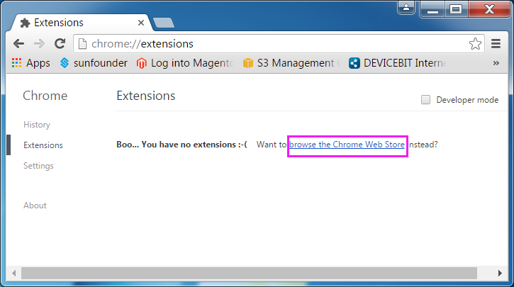
And you'll see the shop page as below:

Step 4: Type in Betaflight in the search bar, select Apps and press Enter. You will see the Betaflight app.

Step 5: Click + ADD TO CHROME, and a prompt Add "Betaflight - Configurator" will pop up asking you whether to add the extension or not. Just click Add app.

Step 6: The software installation may take a little time. When it is done, you will see the Betaflight app in Chrome Extensions.

3. Connecting the Aircraft
Step 1: Click Betaflight to run the ground control software (GCS).

Step 2: Connect the SF RACING F3 to the computer with a USB cable. Go to Computer Management -> Device Manager -> Ports (COM & LPT) to check whether the SF RACING F3 is recognized by the computer or not.

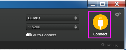
Step 3: If YES, choose the corresponding COM port at the top right corner on the software. Then click Connect.

Step 4: If there is NO driver software on your computer, please install the driver first. Note: If the flight controller is recognized by the computer, please skip this step. 1) The SF RACING F3 flight controller applies STM32 Virtual COM Port (VCP). You can download this driver in Betaflight.

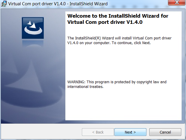
2) After download the driver, double-click VCP_V1.4.0_Setup.exe to install it. After it's completed (click Close), please CONTINUE the installation below.
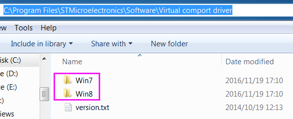
3) Get into C:\Program Files (x86)\STMicroelectronics\Software\Virtual comport driver\Win8\ - Here type in Win7 or Win8 for your computer’s operating system.
You can see there are two files. If your system is 64-bit, please click dpinst_amd64 to install; if it is 32-bit, click dpinst_x86. Wait until the installation is completed.
4) Replug in the USB cable, and then you can see the flight controller is recognized by the computer in the Device Manager.

Click Connect at the top right of the software.
4. Receiver Configuration
The SF RACING F3 supports PWM, PPM, SBUS, and DSM/DSMX; thus you can set your receiver to these modes.
Step 1:
For PWM Signal Mode
If your receiver is in the PWM signal mode, click Configuration on the left, select PWM RX input as Receiver Mode, and then click Save and Reboot.

For PPM Signal Mode
If your receiver is in the PPM signal mode, click Configuration on the left, select PPM RX input as Receiver Mode, and then click Save and Reboot. Under this mode, the least serial ports are occupied and the LED indicator can be set.

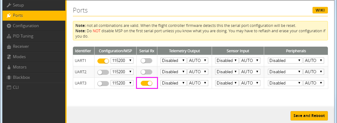
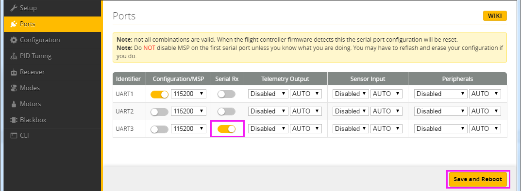
For SBUS Signal Mode The receiver is set under the SBUS signal mode originally. Here SBUS is set as the default RX signal input in Betaflight. So if your receiver is in the SBUS signal mode, there is no need to change the setting of Receiver Mode in Betaflight. Step 2: click Ports on the left, then you can see Serial RX in UART3 has been activated.
Step 3: Next, click Configuration on the left, you will see Receiver Mode is set to Serial-based receiver, and Serial Receiver Provider is SBUS by default.

For DSM Signal Mode:
Step 1: If your receiver is in the DSM/DSMX signal mode, click Ports and enable Serial RX in UART3, then click Save and Reboot.
Step 2: Click Configuration, select RX_SERIAL as Receiver Mode, and select SPEKTRUM1024 in Serial Receiver Provider. After setting, click save and Reboot to save it.

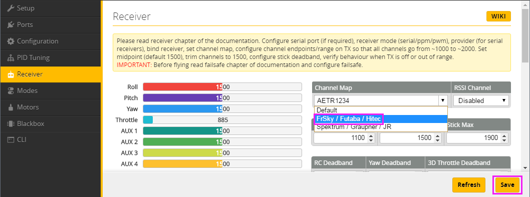
Step 3: Click Receiver on the left, select Futaba/Hitec for Channel Map. Click Save.
5. Pairing
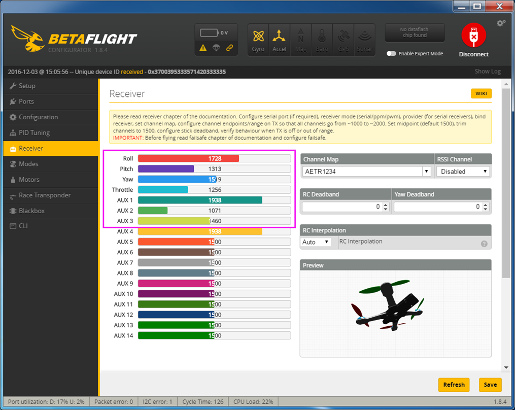
Connect the power cord on the plane with that of the battery, then pair the receiver with the radio transmitter by referring to the attached user manual. Then, click Receiver on the left, pick up the radio transmitter and pull the rocker of throttle or yaw, and you will see the related channel will change accordingly as shown below. Thus you can find the AUX 1 and AUX 2 corresponding rockers. Unplug the power cord of battery after completing.
6. Check Setting in Modes
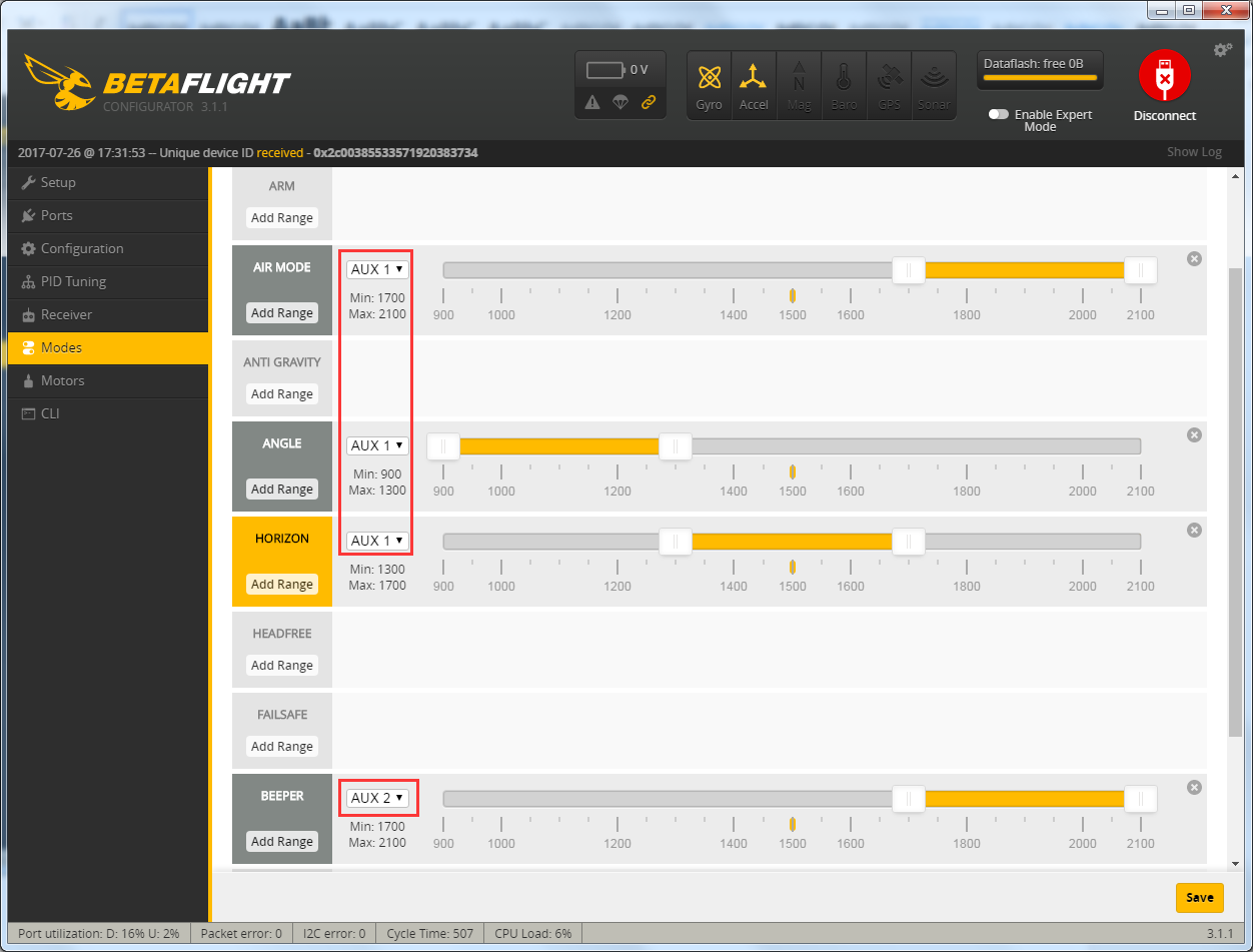
Click Modes on the left, check the setting in red frames are shown as below:
7. Assembled Kit Test
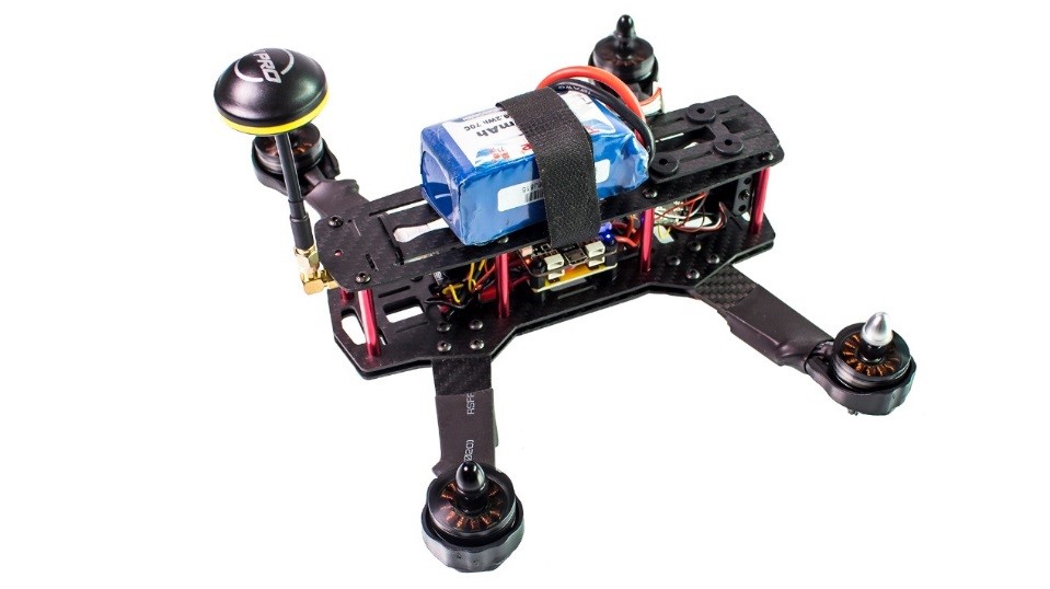
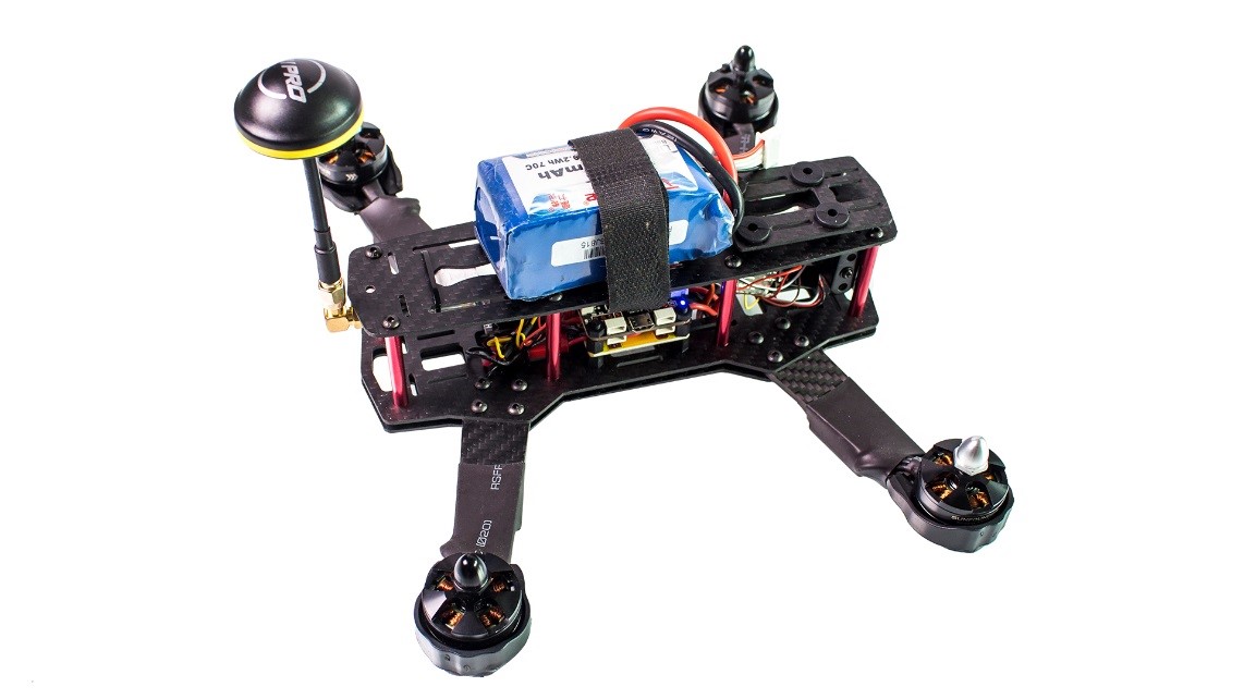
For this assembled kit, you may still need to mount the propellers, mushroom antenna and battery (not included) before flying it. For security reasons, DO NOT mount the propellers in this step to prevent accidents in later test.
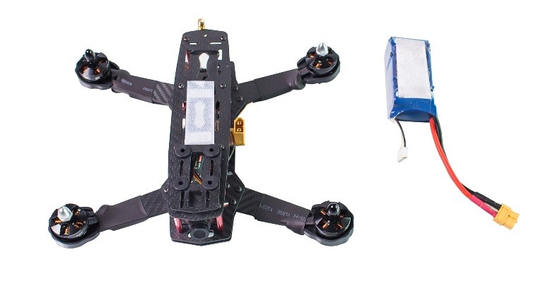
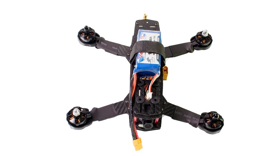
1) Please prepare two pieces of velcro tape (not included), each slightly shorter than the battery, and paste the two pieces on the center of the frame and the back of the battery separately (as shown in Figure 4-1); place the battery on the velcro tape area of the frame, and fix it with a battery strap (not included) (as shown in Figure 4-2).
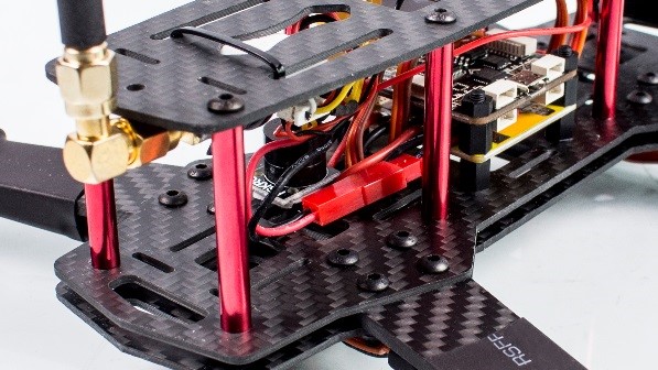
2) Mount the mushroom antenna to the airplane by connect it to the antenna port on the tail part. Then make sure the transceiver kit is well connected to power (as shown in Figure 4-4).

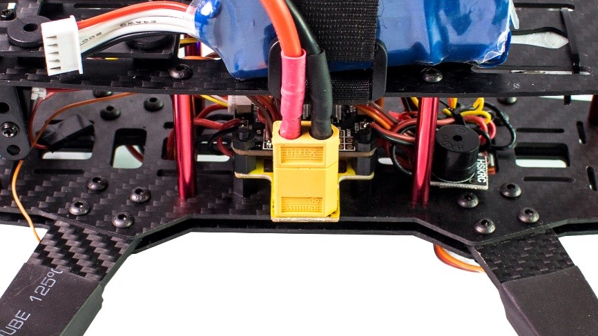
3) Turn on the transmitter (Figure 4-5). Then power on the aircraft: connect the power cord on the plane with that of the battery (Figure 4-6).
 File:033.png
8. Operation Guide for the Image Transmission Board
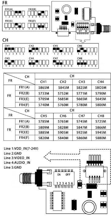
There are six switches on the image transmission board: the No.1, No.2 and No. 3 switches correspond to the channel and the No. 4 and No. 5 switches correspond to the frequency as shown in the table. And there are two buttons on the back of the displayer, one for the frequency and the other for the channel.
For example, if you toggle the No.1, No.2 and No. 3 switches upward, which represents CH1 according to the table, and then toggle the No. 4 and No. 5 switches upward, which represents FR1, then press the channel button to No. 1 and the frequency button to No.1. Likewise, if you toggle the No. 4 switch upward and the No. 5 switch downward, which means FR3, and toggle the No.1, No.2, and No.3 switches downward, which means CH8, then press the frequency button to No.3 and the channel button to No. 8. There is no order of pressing the frequency button or the channel button. Pay attention to maintain the frequency consistent with the channel based on the table. Otherwise, there would be no signal on the displayer.
9. Unlock the plane
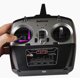
1) Pull the Throttle stick to the bottom and then rightmost (as shown in Figure 4-6), keep this status for 1 second, and you can see the red light on the flight controller blinks once, then keep constantly on (with two slow beeping sounds); Release the Throttle. Now the aircraft is unlocked successfully. Note: The drone will be locked again automatically if there is no operation on the throttle in 5 seconds.
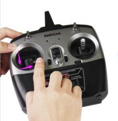
2) Pull the Throttle upward slightly (Figure 4-7), and you can see the motor starts to spin. Note: If you have mounted the propellers unconsciously, DO NOT pull the Throttle stick rapidly, because it’s very DANGEROUS!!!
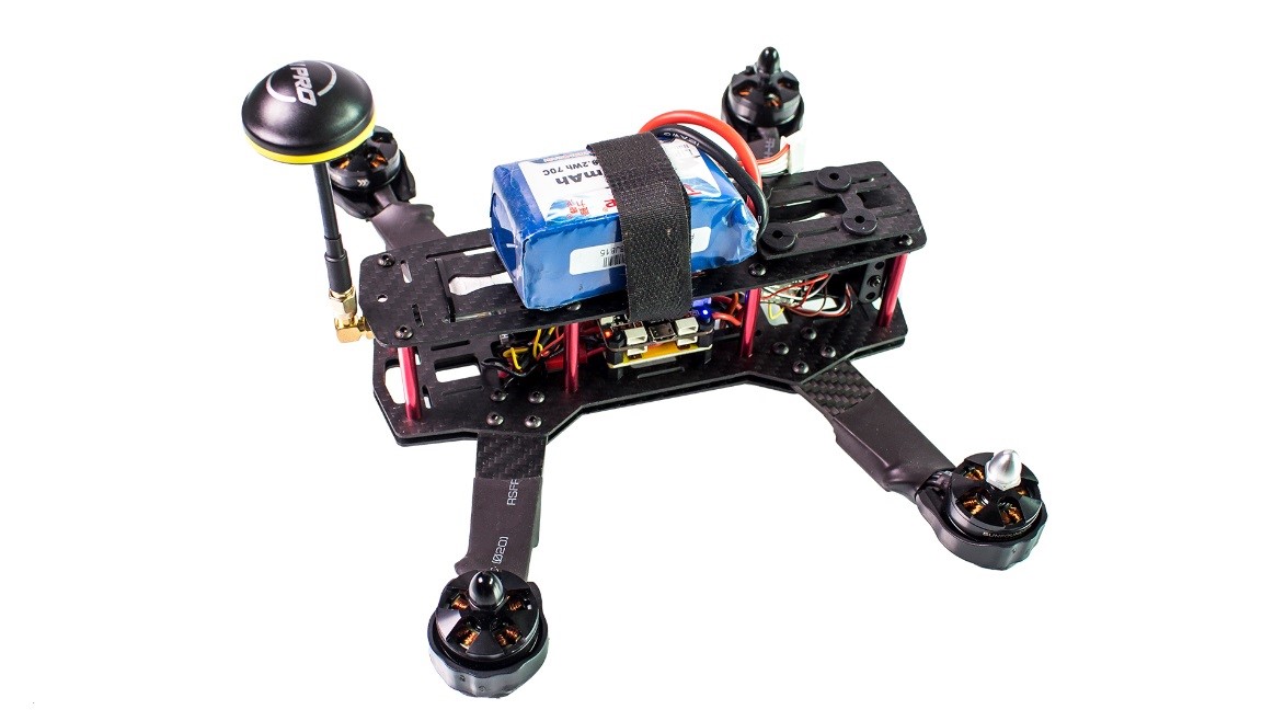
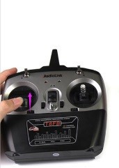
3) Pull the Throttle to the bottom and then leftmost (Figure 4-8), and keep for 1 seconds; when the red light dim (with two fast beeping sounds), release it. Then the aircraft is locked. Note: If the radio transmitter is turned off after first unlocking, the Signal Loss Alarm will beep continuously. Don’t worry, the drone is in lost mode. This function will help you find your lost drone in time if the radio transmitter is out of power and further affect the drone losing control and crashing.
10. Signal Loss Alarm Test

When you slide the AUX2 switch to Max, the alarm will beep; when you slide the switch to Min, it will stop beeping.
11. Trial Flight
If all previous tests work fine, just mount the propellers to start the trial flight.
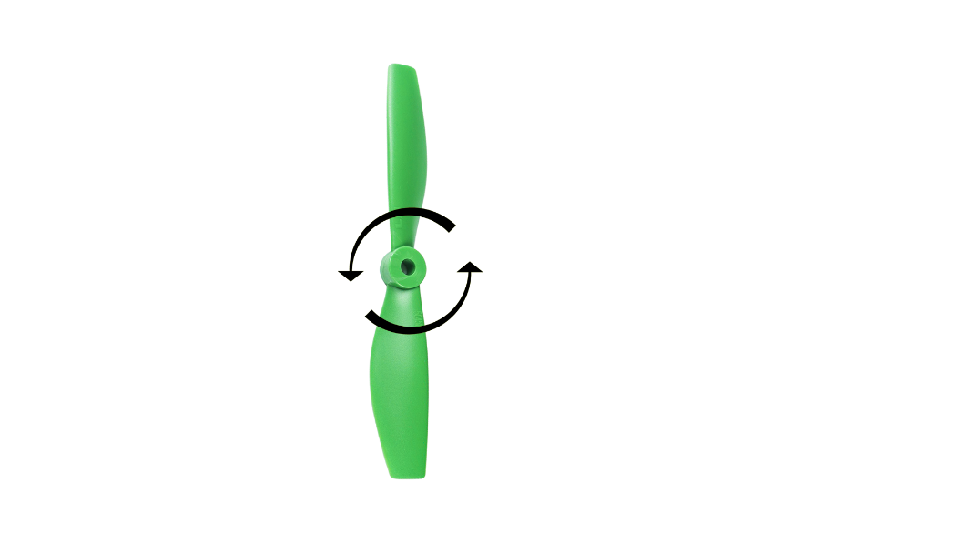
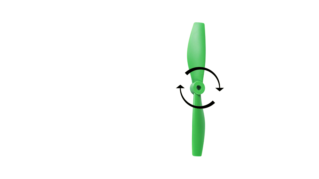
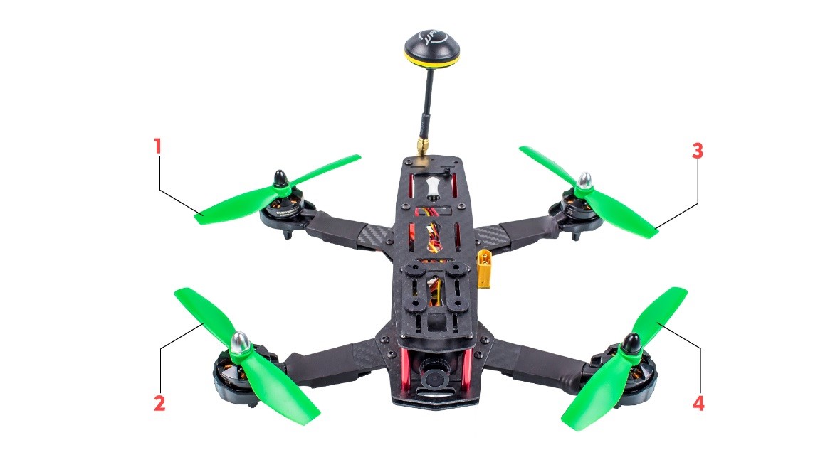
There are two types propellers: CW propeller (Figure 5-1) and CCW propeller (as shown in Figure 5-2). Remember to distinguish the propeller types and mount them as shown in Figure 5-3, with the CW props at No. 1 & 4 and CCW ones at 2 & 3, then fix them with black or white bullet caps separately.
