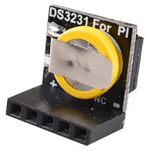
Difference between revisions of "DS3231 Real Time Clock Module for Raspberry Pi"
(→Pin Function=) |
(→Resource) |
||
| (6 intermediate revisions by the same user not shown) | |||
| Line 30: | Line 30: | ||
{| border="1" class="wikitable" | {| border="1" class="wikitable" | ||
| − | + | !scope="col" |PIN | |
| − | + | !scope="col" |NAME | |
| − | + | !scope="col" |FUNCTION | |
|- | |- | ||
|1 | |1 | ||
| Line 78: | Line 78: | ||
=='''Resource'''== | =='''Resource'''== | ||
| − | [http:// | + | [http://wiki.sunfounder.cc/images/d/d9/RTC_SDL_DS3231.zip RTC DS3231 Test Code] [[File:ZIP.jpg]]<br> |
| − | [http:// | + | [http://wiki.sunfounder.cc/images/5/5a/DS3231_datasheet.pdf DS3231_datasheet.pdf][[File:PDF.jpg]] |
Latest revision as of 07:34, 20 March 2017
Description
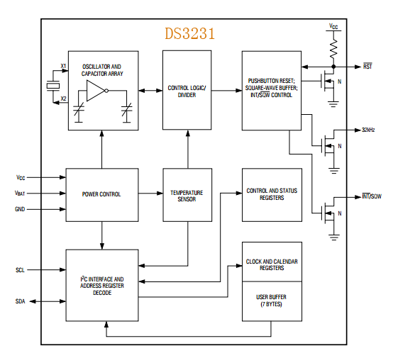
The DS3231 is a low-cost, extremely accurate I2C realtime clock (RTC) with an integrated temperaturecompensated crystal oscillator (TCXO) and crystal. The
device incorporates a battery input, and maintains accurate timekeeping when main power to the device is interrupted. The integration of the crystal resonator enhances the long-term accuracy of the device as well as reduces the piece-part count in a manufacturing line.
The DS3231 is available in commercial and industrial temperature ranges, and is offered in a 16-pin, 300-mil SO package. The RTC maintains seconds, minutes, hours, day, date, month, and year information. The date at the end of the month is automatically adjusted for months with fewer than 31 days, including corrections for leap year. The clock operates in either the 24-hour or 12-hour format with an AM/PM indicator. Two programmable time-ofday alarms and a programmable square-wave output are provided. Address and data are transferred serially through an I2C bidirectional bus.
A precision temperature-compensated voltage reference and comparator circuit monitors the status of VCC to detect power failures, to provide a reset output, and
to automatically switch to the backup supply when necessary. Additionally, the RST pin is monitored as a pushbutton input for generating a reset externally.


Features
♦ Accuracy ±2ppm from 0°C to +40°C
♦ Accuracy ±3.5ppm from -40°C to +85°C
♦ Battery Backup Input for Continuous Timekeeping
♦ Operating Temperature Ranges
- Commercial: 0°C to +70°C
- Industrial: -40°C to +85°C
♦ Low-Power Consumption
♦ Real-Time Clock Counts Seconds, Minutes,Hours, Day, Date, Month, and Year with Leap Year Compensation Valid Up to 2100
♦ Two Time-of-Day Alarms
♦ Programmable Square-Wave Output
♦ Fast (400kHz) I2C Interface
♦ 3.3V Operation
♦ Digital Temp Sensor Output: ±3°C Accuracy
♦ Register for Aging Trim
♦ RST Input/Output
♦ UL Recognized
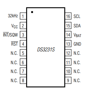
Pin Function=
| PIN | NAME | FUNCTION |
|---|---|---|
| 1 | 32KHZ | 32kHz Output. This open-drain pin requires an external pullup resistor. It may be left open if not used. |
| 2 | VCC | DC Power Pin for Primary Power Supply. This pin should be decoupled using a 0.1µF to 1.0µF capacitor. If not used, connect to ground. |
| 3 | INT/SQW | Active-Low Interrupt or Square-Wave Output. This open-drain pin requires an external pullup resistor. It may be left open if not used. This multifunction pin is determined by the state of the INTCN bit in the Control Register (0Eh). When INTCN is set to logic 0, this pin outputs a square wave and its frequency is determined by RS2 and RS1 bits. When INTCN is set to logic 1, then a match between the timekeeping registers and either of the alarm registers activates the INT/SQW pin (if the alarm is enabled). Because the INTCN bit is set to logic 1 when power is first applied, the pin defaults to an interrupt output with alarms disabled. |
| 4 | RST | Active-Low Reset. This pin is an open-drain input/output. It indicates the status of VCC relative to the VPF specification. As VCC falls below VPF, the RST pin is driven low. When VCC exceeds VPF, for tRST, the RST pin is driven high impedance. The active-low, open-drain output is combined with a debounced pushbutton input function. This pin can be activated by a pushbutton reset request. It has an internal 50kΩ nominal value pullup resistor to VCC. No external pullup resistors should be connected. If the crystal oscillator is disabled, the startup time of the oscillator is added to the tRST delay. |
| 5-12 | N.C. | No Connection. Must be connected to ground. |
| 13 | GND | ground |
| 14 | VBAT | Backup Power-Supply Input. This pin should be decoupled using a 0.1µF to 1.0µF low-leakage capacitor.If the I2C interface is inactive whenever the device is powered by the VBAT input, the decoupling capacitor is not required. If VBAT is not used, connect to ground. UL recognized to ensure against reverse charging when used with a lithium battery. |
| 15 | SDA | Serial Data Input/Output. This pin is the data input/output for the I2C serial interface. This open-drain pin requires an external pullup resistor. |
| 16 | SCL | Serial Clock Input. This pin is the clock input for the I2C serial interface and is used to synchronize data movement on the serial interface. |

