Difference between revisions of "7 Inch Screen Manual"
(→SPECIFICATION) |
(→Resource) |
||
| (9 intermediate revisions by the same user not shown) | |||
| Line 189: | Line 189: | ||
Note: Absolute maximum ratings means the product can withstand short-term, not more than 120 hours. If the product is a long time to withstand these conditions, the life time would be shorter. | Note: Absolute maximum ratings means the product can withstand short-term, not more than 120 hours. If the product is a long time to withstand these conditions, the life time would be shorter. | ||
{|class="wikitable" | {|class="wikitable" | ||
| − | |+ | + | |+ |
|Parameter of DC characteristics | |Parameter of DC characteristics | ||
|Symbol | |Symbol | ||
| Line 239: | Line 239: | ||
|V | |V | ||
|} | |} | ||
| + | '''3、 CTP CHARACTERISTICS''' | ||
| + | <br> | ||
| + | {|class="wikitable" | ||
| + | |- | ||
| + | |Item of CTP characteristics | ||
| + | |Specification | ||
| + | |Unit | ||
| + | |Remark | ||
| + | |- | ||
| + | |Panel Type | ||
| + | |Glass Cover + Glass Sensor | ||
| + | |` | ||
| + | |` | ||
| + | |- | ||
| + | |Resolution | ||
| + | |1024 × 600 | ||
| + | |pixel | ||
| + | |` | ||
| + | |- | ||
| + | |Surface Hardness | ||
| + | |≥6H | ||
| + | |` | ||
| + | |` | ||
| + | |- | ||
| + | |Transparency | ||
| + | |>82% | ||
| + | |` | ||
| + | |` | ||
| + | |- | ||
| + | |Driver IC | ||
| + | |` | ||
| + | |` | ||
| + | |` | ||
| + | |- | ||
| + | |Interface Type | ||
| + | |USB | ||
| + | |` | ||
| + | |` | ||
| + | |- | ||
| + | |Support Points | ||
| + | |5 | ||
| + | |` | ||
| + | |` | ||
| + | |- | ||
| + | |Sampling Rate | ||
| + | |20~100 | ||
| + | |Hz | ||
| + | |` | ||
| + | |- | ||
| + | |Supply voltage | ||
| + | |3.3 | ||
| + | |V | ||
| + | |` | ||
| + | |} | ||
| + | '''4、 INTERFACE DESCRIPTION''' | ||
| + | <br> | ||
| + | {|class="wikitable" | ||
| + | |- | ||
| + | |Symbol | ||
| + | |DESCRIPTION | ||
| + | |- | ||
| + | |VUSB | ||
| + | |USB Power | ||
| + | |- | ||
| + | |D- | ||
| + | |USB Data | ||
| + | |- | ||
| + | |D+ | ||
| + | |USB Data+ | ||
| + | |- | ||
| + | |NC | ||
| + | |No connection | ||
| + | |- | ||
| + | |GND | ||
| + | |Power Ground | ||
| + | |} | ||
| + | '''HDMI Interface Description''' | ||
| + | <br> | ||
| + | {|class="wikitable" | ||
| + | |- | ||
| + | |NO. | ||
| + | |Symbol | ||
| + | |DESCRIPTION | ||
| + | |- | ||
| + | |1 | ||
| + | |DESCRIPTION | ||
| + | |Positive side of channel 2 TMDS low-voltage signal differential input pair | ||
| + | |- | ||
| + | |2 | ||
| + | |TMDS Data2 Shield | ||
| + | |Ground | ||
| + | |- | ||
| + | |3 | ||
| + | |TMDS Data2- | ||
| + | |Negative side of channel 2 TMDS low-voltage signal differential input pair | ||
| + | |- | ||
| + | |4 | ||
| + | |TMDS Data1+ | ||
| + | |Positive side of channel 1 TMDS low-voltage signal differential input pair | ||
| + | |- | ||
| + | |5 | ||
| + | |TMDS Data1 Shield | ||
| + | |Ground | ||
| + | |- | ||
| + | |6 | ||
| + | |TMDS Data1- | ||
| + | |Negative side of channel 1 TMDS low-voltage signal differential input pair | ||
| + | |- | ||
| + | |7 | ||
| + | |TMDS Data0+ | ||
| + | |Positive side of channel 0 TMDS low-voltage signal differential input pair | ||
| + | |- | ||
| + | |8 | ||
| + | |TMDS Data0 Shield | ||
| + | |Ground | ||
| + | |- | ||
| + | |9 | ||
| + | |TMDS Data0- | ||
| + | |Negative side of channel 0 TMDS low-voltage signal differential input pair | ||
| + | |- | ||
| + | |10 | ||
| + | |TMDS Clock+ | ||
| + | |Positive side of reference clock. TMDS low-voltage signal differential input pair | ||
| + | |- | ||
| + | |11 | ||
| + | |TMDS Clock Shield | ||
| + | |Ground | ||
| + | |- | ||
| + | |12 | ||
| + | |TMDS Clock | ||
| + | |Negative side of reference clock. TMDS low-voltage signal differential input pair | ||
| + | |- | ||
| + | |13 | ||
| + | |CEC | ||
| + | |No Connection | ||
| + | |- | ||
| + | |14 | ||
| + | |Reserved(N.C.) | ||
| + | |No Connection | ||
| + | |- | ||
| + | |15 | ||
| + | |SCL | ||
| + | |DDC SCL | ||
| + | |- | ||
| + | |16 | ||
| + | |SDA | ||
| + | |DDC SDA | ||
| + | |- | ||
| + | |17 | ||
| + | |DDC/CEC Ground | ||
| + | |Ground | ||
| + | |- | ||
| + | |18 | ||
| + | |+5V Power | ||
| + | |+5V Power | ||
| + | |- | ||
| + | |19 | ||
| + | |Hot Plug Detect | ||
| + | |Hot Plug Detect | ||
| + | |} | ||
| + | '''B、 USB Interface Description Application Note: Please connect the USB first, and then connect the HDMI interface.''' | ||
| + | =='''Resource'''== | ||
| + | [http://wiki.sunfounder.cc/images/1/16/7_Inch_Screen_Manual.pdf Editing_7_Inch_Screen_Manual.pdf][[File:PDF.jpg]]<br> | ||
Latest revision as of 10:29, 22 October 2019
Contents
[hide]7 Inch DIY Touch Screen
Supporting the Seven-inch Screen
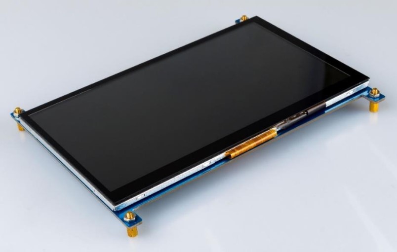
Use a nut (M3) and a copper post (M3 * 8 + 6) to support the seven-inch touch screen.
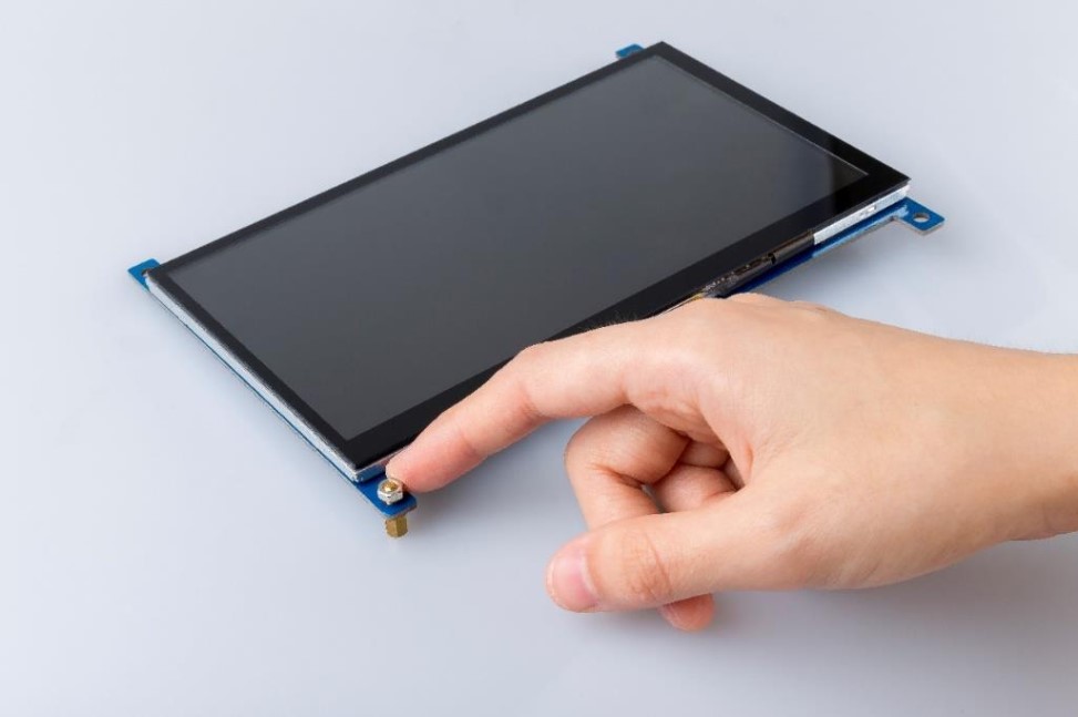
Rendering
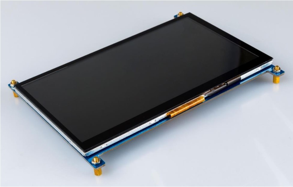
This 7-inch touch screen is compatible with any version of the Raspberry Pi.
With a Raspberry Pi 4
Connect the Raspberry Pi 4 to HDMI with a micro HDMI cable.
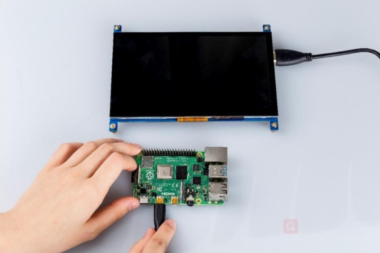
Wire the USB cable up to Raspberry Pi 4.
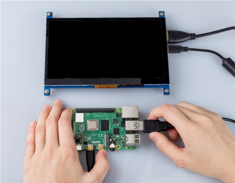
Give it a power supply, Plug and play.
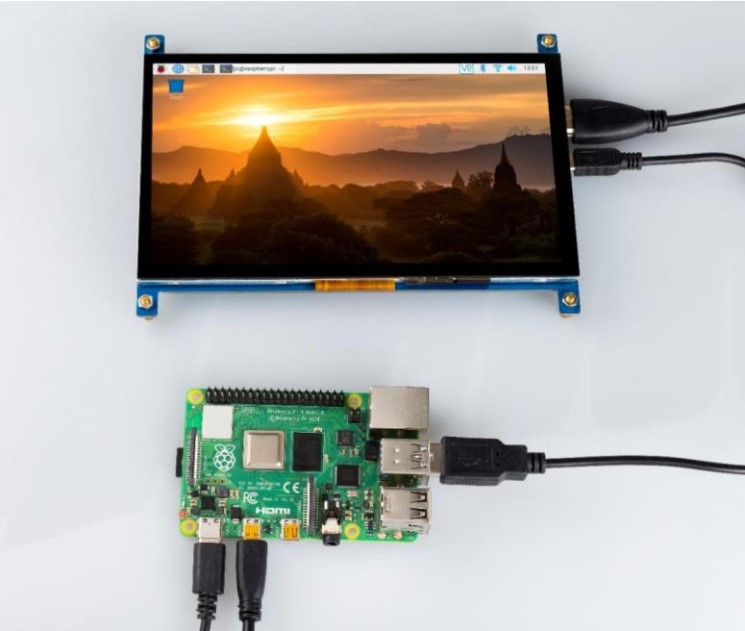
Adjust the Resolution of Raspberry Pi 4
Step 1: Unfold the menu bar of Raspberry Pi.
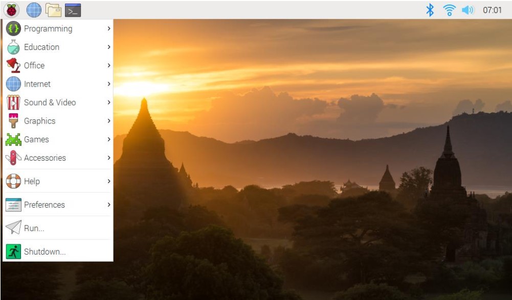
Step 2: Select screen configuration.
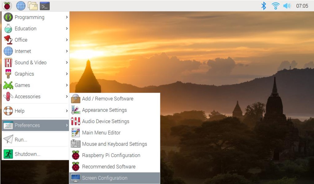
Step 3: Select screen configuration.
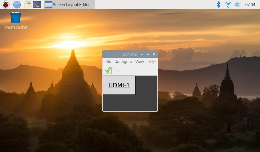
Step 4: Select Screens.
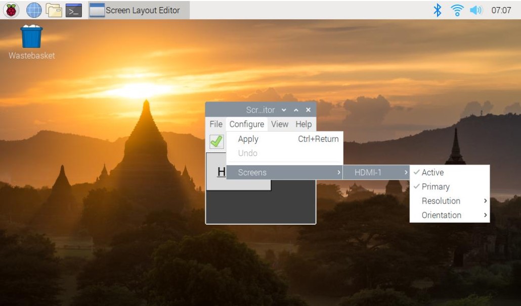
Step 5: Choose the resolution you want.
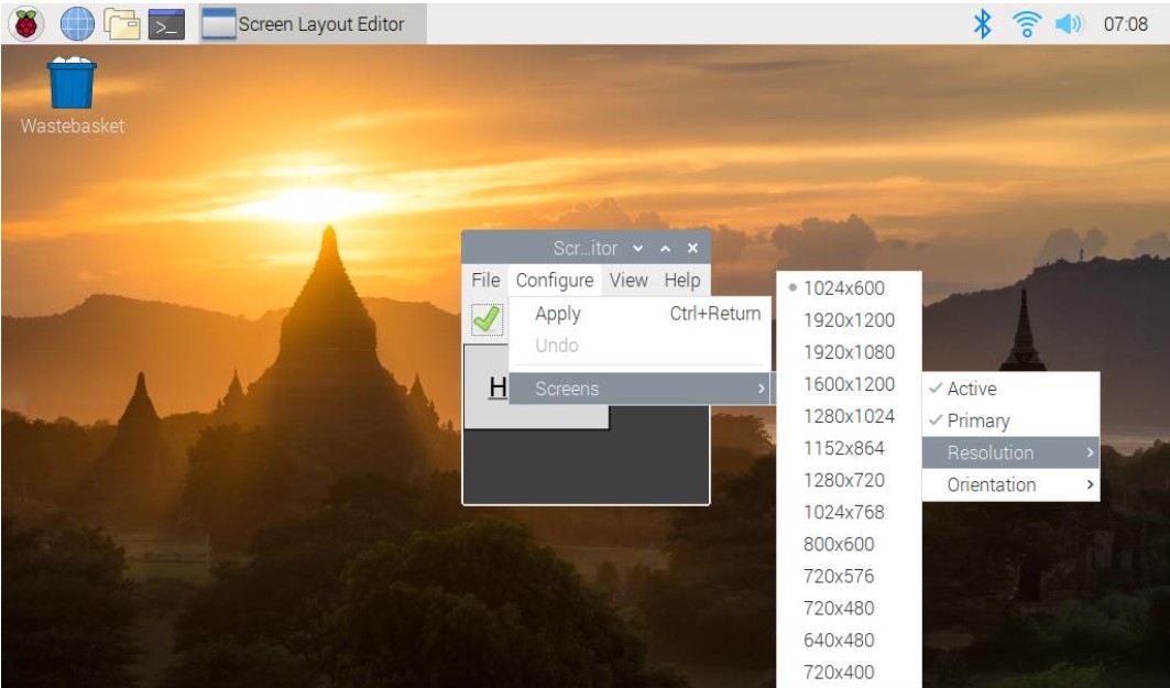
With a Raspberry Pi 3
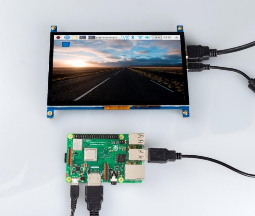
Plug a dual-head HDMI cable in Raspberry Pi 3.
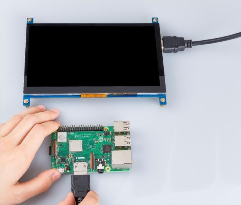
Connect the Raspberry Pi 3 with a USB cable.
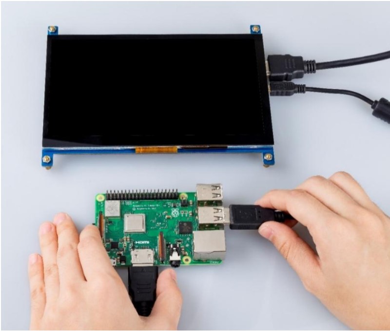
Attach a power supply to it, turn it on.
Adjust the Resolution of Raspberry Pi 3
Step 1: Open config.txt
There are two methods to do so.
Method A: First prepare a computer on Windows, Mac or Linux, and a TF card on which the Raspbian system has been burnt. Plug the TF card into the computer with a card reader. Now, open /boot and find the config.txt file. If your computer runs on Windows, DO NOT open the file by Word (also better not notepad) in case of format issues. You are advised to use other edit tools like Notepad++ .
Method B: Log in to Raspberry Pi remotely. Run the command to edit config.txt.
sudo nano /boot/config.txt
Step 2: Modify the /boot/config.txt file
In either way, now the file config.txt is opened.
1) Define a custom CVT mode (since Raspberry Pi uses the standard rate when 1024x600 is not included, you need to set the aspect ratio as 16:9, i.e. 1024x576) add the following lines below #hdmi_force_hotplug=1.
hdmi_cvt=1024 576 60 3 0 0 0
hdmi_cvt=<width> <height> <framerate> <aspect> <margins>
<interlace>
| Value | Default | Description |
| width | (required) | width in pixels |
| height | (required) | height in pixels |
| height in pixels | (required) | framerate in Hz |
| aspect | 3 | aspect ratio 1=4:3, 2=14:9, 3=16:9, 4=5:4,5=16:10, 6=15:9 |
| margins | 0 | 0=margins disabled, 1=margins enabled |
| interlace | 0 | 0=progressive, 1=interlaced |
| rb | 0 | 0=normal, 1=reduced blanking |
2) Find the following lines (If there is a "#" mark at the beginning of any of the three lines, which means they are comments, delete the mark. The asterisk "*" represents the value.
hdmi_group=*
hdmi_mode=*
hdmi_drive=*
3) Modify the value, like this:
hdmi_group=2
hdmi_mode=87
....
hdmi_drive=2
hdmi_group=2 means DMT (Display Monitor Timings; the standard typically used by monitors)
hdmi_mode=87 indicates the resolution bit.
hdmi_drive=2 selects the Normal HDMI mode.
For more details about configuring config.txt, refer to Raspberry Pi official
website: https://www.raspberrypi.org/documentation/configuration/config-txt.md.
After the modification is done, save and exit.
Step 3: Connect Raspberry Pi
If you change the commands on your PC, after mounting the TF card safely, plug it into the Raspberry Pi. Then connect the power of the Raspberry Pi and the display.
If you log in the Raspberry Pi remotely with ssh, type in the command sudo reboot.
SPECIFICATION
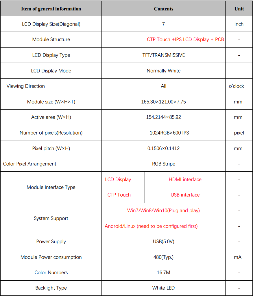
1、 GENERAL INFORMATION
2、 ABSOLUTE MAXIMUM RATINGS
| Parameter of absolute maximum ratings | Symbol | Min | Max | Unit |
| Operating temperature | Top | -10 | 60 | 60 |
| Storage temperature | Tst | -20 | 70 | ℃ |
| Humidity | RH | ` | 90%(Max 60℃) | RH |
Note: Absolute maximum ratings means the product can withstand short-term, not more than 120 hours. If the product is a long time to withstand these conditions, the life time would be shorter.
| Parameter of DC characteristics | Symbol | Min. | Min. | Max. | Unit |
| PCB operating voltage | VUSB | ` | 5.0 | ` | V |
| LCD I/O operating voltage | VDD | 3.0 | 3.3 | 3.6 | V |
| Input voltage ‘H’ level | VIH | 0.7*VDD | ` | VDD | V |
| Input voltage ‘L’ level | VIL | VSS | ` | 0.3*VDD | V |
| Output voltage ‘H’ level | VOH | VDD-0.4 | ` | VDD | V |
| Output voltage ‘L’ level | VOL | VSS | ` | VSS+0.4 | V |
3、 CTP CHARACTERISTICS
| Item of CTP characteristics | Specification | Unit | Remark |
| Panel Type | Glass Cover + Glass Sensor | ` | ` |
| Resolution | 1024 × 600 | pixel | ` |
| Surface Hardness | ≥6H | ` | ` |
| Transparency | >82% | ` | ` |
| Driver IC | ` | ` | ` |
| Interface Type | USB | ` | ` |
| Support Points | 5 | ` | ` |
| Sampling Rate | 20~100 | Hz | ` |
| Supply voltage | 3.3 | V | ` |
4、 INTERFACE DESCRIPTION
| Symbol | DESCRIPTION |
| VUSB | USB Power |
| D- | USB Data |
| D+ | USB Data+ |
| NC | No connection |
| GND | Power Ground |
HDMI Interface Description
| NO. | Symbol | DESCRIPTION |
| 1 | DESCRIPTION | Positive side of channel 2 TMDS low-voltage signal differential input pair |
| 2 | TMDS Data2 Shield | Ground |
| 3 | TMDS Data2- | Negative side of channel 2 TMDS low-voltage signal differential input pair |
| 4 | TMDS Data1+ | Positive side of channel 1 TMDS low-voltage signal differential input pair |
| 5 | TMDS Data1 Shield | Ground |
| 6 | TMDS Data1- | Negative side of channel 1 TMDS low-voltage signal differential input pair |
| 7 | TMDS Data0+ | Positive side of channel 0 TMDS low-voltage signal differential input pair |
| 8 | TMDS Data0 Shield | Ground |
| 9 | TMDS Data0- | Negative side of channel 0 TMDS low-voltage signal differential input pair |
| 10 | TMDS Clock+ | Positive side of reference clock. TMDS low-voltage signal differential input pair |
| 11 | TMDS Clock Shield | Ground |
| 12 | TMDS Clock | Negative side of reference clock. TMDS low-voltage signal differential input pair |
| 13 | CEC | No Connection |
| 14 | Reserved(N.C.) | No Connection |
| 15 | SCL | DDC SCL |
| 16 | SDA | DDC SDA |
| 17 | DDC/CEC Ground | Ground |
| 18 | +5V Power | +5V Power |
| 19 | Hot Plug Detect | Hot Plug Detect |
B、 USB Interface Description Application Note: Please connect the USB first, and then connect the HDMI interface.
