Difference between revisions of "DS18B20 Temperature Sensor Module"
| Line 33: | Line 33: | ||
*'''Installing the DallasTemperature Library'''<br> | *'''Installing the DallasTemperature Library'''<br> | ||
| − | Click here to download the DallasTemperature library. You should have a .zip folder in your Downloads.<br> | + | Click [http://wiki.sunfounder.cc/images/3/34/DallasTemperature.zip here]to download the DallasTemperature library. You should have a .zip folder in your Downloads.<br> |
Open Arduino IDE, then click Sketch -> Include Library -> Add ZIP Library, and select DallasTemperature.zip to include.<br> | Open Arduino IDE, then click Sketch -> Include Library -> Add ZIP Library, and select DallasTemperature.zip to include.<br> | ||
After including successfully, you can see the example in File -> Examples -> DallasTemperature.<br> | After including successfully, you can see the example in File -> Examples -> DallasTemperature.<br> | ||
Latest revision as of 02:42, 17 September 2019
Contents
[hide]Introduction
DS18B20 digital temperature sensor works on a single bus and it has 64-bit ROM to store the serial number of component. It can get quite a few DS18B20 sensors connected to a single bus in parallel. With a microcontroller, you can control so many DS18B20 sensors that are distributed around a wide range. So the sensor is widely used in these fields, including HVAC environmental control, temperature detection of building, instrument and machine, and process monitoring and control. The number of sensors in the parallel connection cannot be over 8; otherwise, brownout will happen and the signal transmission will turn to be unstable. As a result, multi-point temperature measurement will fail.
Main Features
- Working Voltage: 3V~5.5V
- Detected Temperature Range: -55°C~+125°C (-67°F~+257°F) deviation ±2°C ,-10°C~+85°C deviation ±0.5°C
- Panel Size: 21mm x 10mm
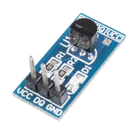
Introduction of the Pins
- VCC: 3.3V-5V working voltage
- DQ : data input/ output pin
- GND: ground
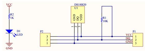
Principle
For Arduino
Using Steps
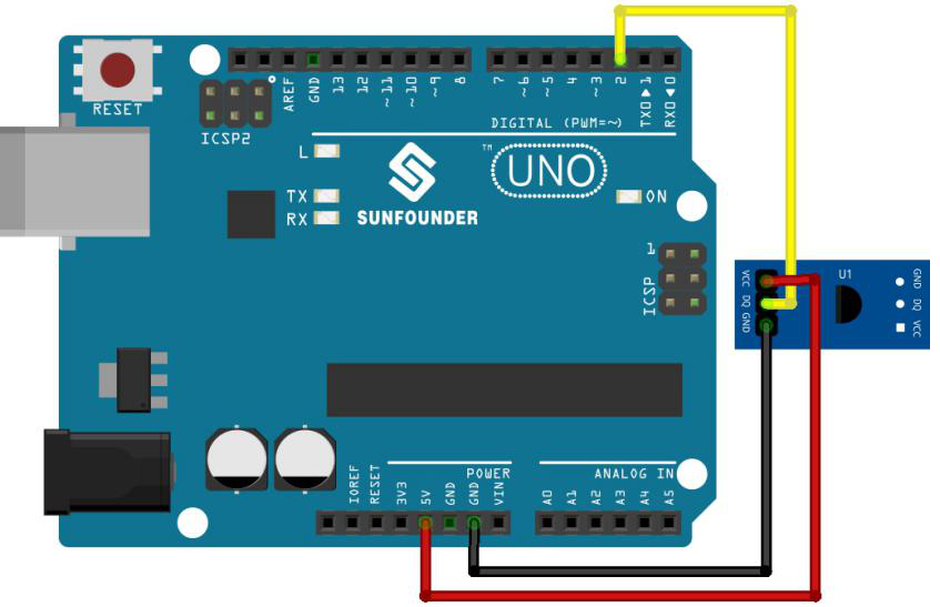
Step 1: Connect the circuit.
Step 2: Download and Add library
- Installing the OneWire Library
Click hereto download the OneWire library. You should have a .zip folder in your Downloads.
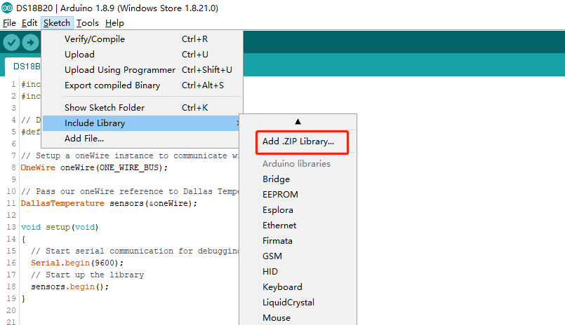
Open Arduino IDE, then click Sketch -> Include Library -> Add ZIP Library, and select OneWire.zip to include.
After including successfully, you can see the example in File -> Examples -> OneWire.
- Installing the DallasTemperature Library
Click hereto download the DallasTemperature library. You should have a .zip folder in your Downloads.
Open Arduino IDE, then click Sketch -> Include Library -> Add ZIP Library, and select DallasTemperature.zip to include.
After including successfully, you can see the example in File -> Examples -> DallasTemperature.
Step 3: Copy the following codes and paste them in Arduino
///Arduino Sample Code
#include <OneWire.h>
#include <DallasTemperature.h>

// Data wire is conntec to the Arduino digital pin 2
#define ONE_WIRE_BUS 2

// Setup a oneWire instance to communicate with any OneWire devices
OneWire oneWire(ONE_WIRE_BUS);

// Pass our oneWire reference to Dallas Temperature sensor
DallasTemperature sensors(&oneWire);

void setup(void)
{
  // Start serial communication for debugging purposes
  Serial.begin(9600);
  // Start up the library
  sensors.begin();
}
void loop(void)
{
  // Call sensors.requestTemperatures() to issue a global temperature and Requests to all devices on the bus
  sensors.requestTemperatures();
  Serial.print("Celsius: ");
  // Why "byIndex"? You can have more than one IC on the same bus. 0 refers to the first IC on the wire
  Serial.print(sensors.getTempCByIndex(0));
  Serial.print(" - Fahrenheit: ");
  Serial.println(sensors.getTempFByIndex(0));
  delay(1000);
}
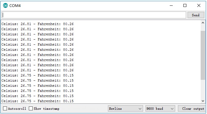
On Serial Monitor, choose the baud rate 9600, and you can see the centigrade temperature and Fahrenheit temperature.
