Difference between revisions of "E18-D80NK Infrared Photoelectric Switch Sensor"
(→Experimental Procedures for Arduino) |
(→Experimental Procedures for Arduino) |
||
| (3 intermediate revisions by the same user not shown) | |||
| Line 53: | Line 53: | ||
|} | |} | ||
<br> | <br> | ||
| − | < | + | <pre> |
const int e18Pin = 2; | const int e18Pin = 2; | ||
int statusVal = 0; | int statusVal = 0; | ||
| Line 72: | Line 72: | ||
} | } | ||
| − | < | + | </pre> |
| + | When the obstacles are detected, the serial port will output “Collision Detected”; or else, it outputs “No Collision Detected”. <br> | ||
| + | [[File:E18-D80NK_COM.png]]<br> | ||
| + | As referred in experiment, the color of ground or wall or any material used to reflect lights to the sensor is not dark enough. If the wall is in light color, the least detection distance of Sensor is also get higher; so, the specified detection distance of users is lower than the least detection distance of Sensor. This case needs the wall in dark color or to set the detection distance higher. Users have to test and setup detection distance by themselves because each color get different reflection by Sensor. | ||
Latest revision as of 10:14, 12 September 2019
Contents
Introduction

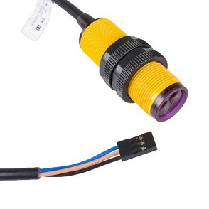
This product, photoelectric sensor integrates emitting and receiving and its detection distance is adjustable. The sensor can detect very long distance free from the interruption of visible light. Owing to the advantages on price, assembly and operation, it is widely applied in so much automatic work, like obstacle avoidance of robot and piecework on assembly line.
Main Features
- Photosensitive Sensor (photoelectric switch) NPN always on;
- Type: E18-D80NK;
- Input Voltage: 5VDC;
- Load Current: 100mA;
- Sensing Distance: Around 80CM;
- Diameter: 18MM;
- Sensor Length: 45MM;
- Lead Length: 45CM.
Introduction of Pins
| Pin Introduction | |
|---|---|
| Blue | GND |
| Brown | VCC |
| Black | OUT |
Working Principle
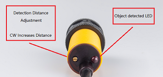
Emitter constantly emits Infra-red Lights to the detected objects. The receiver turns the reflected rays from the detected objects (light energy) into current and transmit it to the back integrated circuit. Then the current is output via the amplifier after being processed by IC. At the rear of the sensor, there is a potentiometer to help adjust the detection distance. When the head of Sensor moves and passes the specified distance detection, LED of Sensor is lit up, and at the same time, the sensor outputs low level signal.

File:Schematic diagram.png
Experimental Procedures for Arduino
Step 1: Connect the circuit:
| E18-D80NK | Uno Board |
| Black | D2 |
| Brown | VCC |
| Blue | GND |
const int e18Pin = 2;
int statusVal = 0;
void setup() {
  // put your setup code here, to run once:
  pinMode(e18Pin,INPUT);
  Serial.begin(9600);
}

void loop() {
  // put your main code here, to run repeatedly:
  statusVal = digitalRead(e18Pin);
  if(statusVal == LOW){
    Serial.println("Collision Detected.");
  }else{
    Serial.println("No Collision Detected.");
  }
}
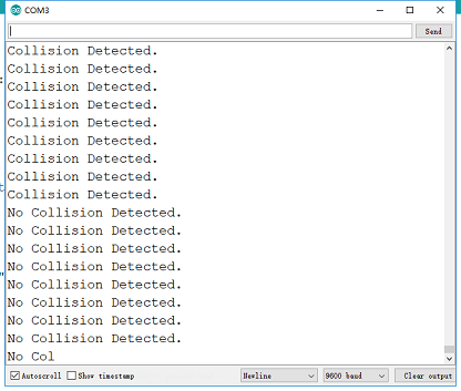
When the obstacles are detected, the serial port will output “Collision Detected”; or else, it outputs “No Collision Detected”.

As referred in experiment, the color of ground or wall or any material used to reflect lights to the sensor is not dark enough. If the wall is in light color, the least detection distance of Sensor is also get higher; so, the specified detection distance of users is lower than the least detection distance of Sensor. This case needs the wall in dark color or to set the detection distance higher. Users have to test and setup detection distance by themselves because each color get different reflection by Sensor.