Difference between revisions of "Collision Switch Module"
From Wiki
(→Introduction of Pins) |
(→Experimental Procedures For Arduino) |
||
| (22 intermediate revisions by the same user not shown) | |||
| Line 9: | Line 9: | ||
<li>Applied in the detection of collision and touching impact.</li> | <li>Applied in the detection of collision and touching impact.</li> | ||
</ul> | </ul> | ||
| + | |||
=='''Introduction of Pins'''== | =='''Introduction of Pins'''== | ||
| − | <table border="5 | + | <table border="5"> |
<tr> | <tr> | ||
<td colspan="2">Introduction of Pins</td> | <td colspan="2">Introduction of Pins</td> | ||
</tr> | </tr> | ||
| − | <tr> | + | <tr> |
| − | <td> | + | <td> |
| − | OUT | + | OUT |
| − | </td> | + | </td> |
| − | <td> | + | <td> |
| − | Switching signal output | + | Switching signal output |
| − | </td> | + | </td> |
| − | </tr> | + | </tr> |
| + | <tr> | ||
| + | <td> | ||
| + | VCC | ||
| + | </td> | ||
| + | <td> | ||
| + | positive pole | ||
| + | </td> | ||
| + | </tr> | ||
| + | <tr> | ||
| + | <td> | ||
| + | GND | ||
| + | </td> | ||
| + | <td> | ||
| + | negative pole | ||
| + | </td> | ||
| + | </tr> | ||
</table> | </table> | ||
| + | =='''principle'''== | ||
| + | Getting an impact, the switch outputs low level, or else it outputs high level.<br> | ||
| + | [[ File:Collision Switch Module schematic diagram.png]]<br> | ||
| + | =='''Experimental Procedures For Arduino '''== | ||
| + | '''Step 1''': Connect the circuit: | ||
| + | {| class="wikitable" | ||
| + | |'''Creshsensor''' | ||
| + | |'''Uno Board''' | ||
| + | |- | ||
| + | |VCC | ||
| + | |5V | ||
| + | |- | ||
| + | |GND | ||
| + | |GND | ||
| + | |- | ||
| + | |D0 | ||
| + | |2 | ||
| + | |} | ||
| + | [[File:Collision Switch Module(Fritzing).png]]<br> | ||
| + | '''Step 2''': Compile and upload the code | ||
| + | Using SunFounder Uno | ||
| + | <pre> | ||
| + | int ledPin = 13; // choose the pin for the LED | ||
| + | int inputPin = 2; // Connect sensor to input pin 3 | ||
| + | |||
| + | |||
| + | void setup() { | ||
| + | Serial.begin(9600); // Init the serial port | ||
| + | |||
| + | pinMode(ledPin, OUTPUT); // declare LED as output | ||
| + | pinMode(inputPin, INPUT); // declare Micro switch as input | ||
| + | } | ||
| + | |||
| + | void loop(){ | ||
| + | int val = digitalRead(inputPin); // read input value | ||
| + | if (val == LOW) { // check if the input is HIGH | ||
| + | digitalWrite(ledPin, HIGH); // turn LED ON | ||
| + | Serial.println("Switch Pressed!"); | ||
| + | } else { | ||
| + | digitalWrite(ledPin, LOW); // turn LED OFF | ||
| + | } | ||
| + | delay(50); | ||
| + | } | ||
| + | |||
| + | </pre> | ||
| + | When the module detects the impact, the serial port will output “Switch Pressed!”Meanwhile, the LED on the pin 13 of the UNO board will light up. | ||
Latest revision as of 09:45, 3 September 2019
Contents
[hide]Introduction
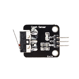
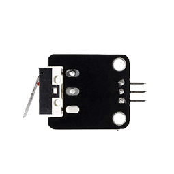
The Crash sensor is a miniature snap-action switch. It is also known as micro switch, an electric switch activated by a small physical force.


feature
- Special module with ports compatible with the expansion board of sensor.
- Output low level when the module is activated; keep outputting high level at the state of release.
- Applied in the detection of collision and touching impact.
Introduction of Pins
| Introduction of Pins | |
OUT |
Switching signal output |
VCC |
positive pole |
GND |
negative pole |
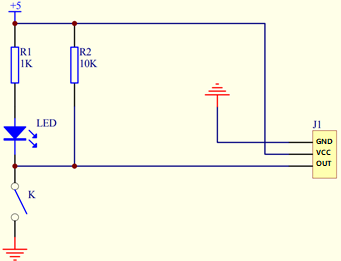
principle
Getting an impact, the switch outputs low level, or else it outputs high level.

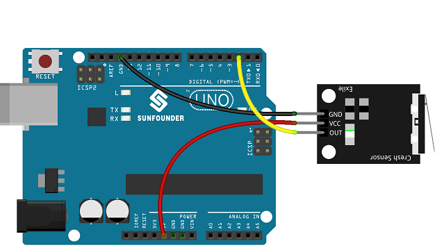
Experimental Procedures For Arduino
Step 1: Connect the circuit:
| Creshsensor | Uno Board |
| VCC | 5V |
| GND | GND |
| D0 | 2 |

Step 2: Compile and upload the code
Using SunFounder Uno
int ledPin = 13;                // choose the pin for the LED
int inputPin = 2;               // Connect sensor to input pin 3


void setup() {
  Serial.begin(9600);           // Init the serial port

  pinMode(ledPin, OUTPUT);      // declare LED as output
  pinMode(inputPin, INPUT);     // declare Micro switch as input
}

void loop(){
  int val = digitalRead(inputPin);  // read input value
  if (val == LOW) {                // check if the input is HIGH
digitalWrite(ledPin, HIGH);      // turn LED ON
Serial.println("Switch Pressed!");
  } else {
    digitalWrite(ledPin, LOW);     // turn LED OFF
  }
  delay(50);
}
When the module detects the impact, the serial port will output “Switch Pressed!”Meanwhile, the LED on the pin 13 of the UNO board will light up.