Difference between revisions of "Digital Accelerometer ADXL345 Module"
(→To use the ADXL345 with Arduino, you can take the following steps.) |
(→To use the ADXL345 with Arduino, you can take the following steps.) |
||
| (One intermediate revision by the same user not shown) | |||
| Line 1: | Line 1: | ||
=='''Introduction'''== | =='''Introduction'''== | ||
[[File:adxl345.png]]<br> | [[File:adxl345.png]]<br> | ||
| − | + | The ADXL345 is a small, thin, low power, 3-axis accelerometer with high resolution (13-bit) measurement at up to ±16 g. Digital output data is formatted as 16-bit two’s complement and is accessible through either an SPI (3- or 4-wire) or I2C digital interface.<br> | |
The ADXL345 is well suited to measure the static acceleration of gravity in tilt-sensing applications, as well as dynamic acceleration resulting from motion or shock. Its high resolution (4 mg/LSB) enables the inclination change measurement by less than 1.0°. And the excellent sensitivity (3.9mg/LSB @2g) provides a high-precision output of up to ±16g.<br> | The ADXL345 is well suited to measure the static acceleration of gravity in tilt-sensing applications, as well as dynamic acceleration resulting from motion or shock. Its high resolution (4 mg/LSB) enables the inclination change measurement by less than 1.0°. And the excellent sensitivity (3.9mg/LSB @2g) provides a high-precision output of up to ±16g.<br> | ||
In this experiment, I2C digital interface is used.<br> | In this experiment, I2C digital interface is used.<br> | ||
| Line 11: | Line 11: | ||
=='''Features'''== | =='''Features'''== | ||
| − | + | ||
Ultra low power: 25 to 130 µA at VS = 2.5 V (typ)<br> | Ultra low power: 25 to 130 µA at VS = 2.5 V (typ)<br> | ||
Power consumption scales automatically with bandwidth<br> | Power consumption scales automatically with bandwidth<br> | ||
| Line 36: | Line 36: | ||
=='''Test'''== | =='''Test'''== | ||
==='''To use the ADXL345 with Arduino, you can take the following steps. '''=== | ==='''To use the ADXL345 with Arduino, you can take the following steps. '''=== | ||
| − | + | '''Step1:'''Connecting circuit | |
| − | + | It can share the I2C bus with other I2C devices as long as each device has a unique address. Only 4 connections are required for I2C communication.<br> | |
:::::::ADXL345 ------- Arduino Uno/Mega2560 | :::::::ADXL345 ------- Arduino Uno/Mega2560 | ||
:::::::: GND --------- GND | :::::::: GND --------- GND | ||
| Line 44: | Line 44: | ||
:::::::: SDA ------- A4 Uno/pin20 Mega2560 | :::::::: SDA ------- A4 Uno/pin20 Mega2560 | ||
[[File:ADXL345_bb.png]]<br> | [[File:ADXL345_bb.png]]<br> | ||
| − | + | '''Step2:''' Upload the code | |
#include <Wire.h> | #include <Wire.h> | ||
#define Register_ID 0 | #define Register_ID 0 | ||
| Line 124: | Line 124: | ||
} | } | ||
| − | + | '''Step3:''' Select correct Board and Port | |
| − | + | '''Step4:''' Upload the sketch to the SunFounder Uno board | |
After uploading, open Serial Monitor, where you can see the data detected. When the acceleration of the module changes, the figure will change accordingly on the window.<br> | After uploading, open Serial Monitor, where you can see the data detected. When the acceleration of the module changes, the figure will change accordingly on the window.<br> | ||
[[File:adxl xinaxiang.jpg]]<br> | [[File:adxl xinaxiang.jpg]]<br> | ||
Latest revision as of 01:49, 13 October 2017
Contents
Introduction
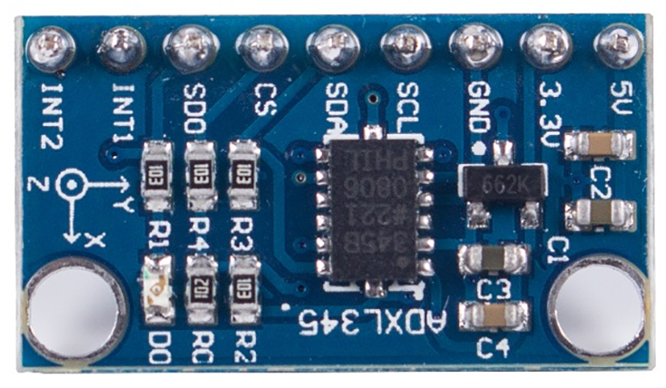
The ADXL345 is a small, thin, low power, 3-axis accelerometer with high resolution (13-bit) measurement at up to ±16 g. Digital output data is formatted as 16-bit two’s complement and is accessible through either an SPI (3- or 4-wire) or I2C digital interface.
The ADXL345 is well suited to measure the static acceleration of gravity in tilt-sensing applications, as well as dynamic acceleration resulting from motion or shock. Its high resolution (4 mg/LSB) enables the inclination change measurement by less than 1.0°. And the excellent sensitivity (3.9mg/LSB @2g) provides a high-precision output of up to ±16g.
In this experiment, I2C digital interface is used.
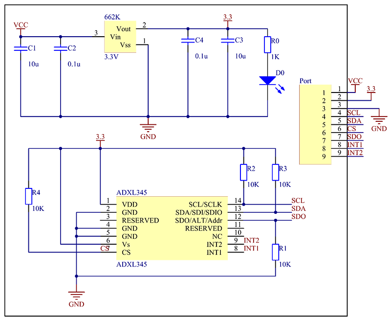
See the following figure for the schematic diagram. There is a 3.3v voltage regulator chip in the circuit, so you can power the module with 5V or 3.3V.
ADXL345 works like this:
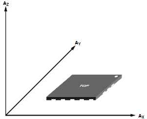
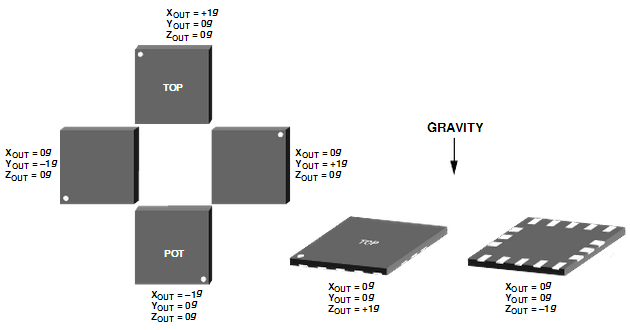
When you place the module face up, Z_OUT is at the maximum which is +1g; face down, Z_OUT is at the minimum. No matter of face, as long as it's placed on a level surface, X_OUT increases along the Ax axis direction, so does Y_OUT along the Ay axis. See the picture below. Thus, when you rotate the module, you can see the changes of X_OUT, Y_OUT, and Z_OUT.
</P>
Features
Ultra low power: 25 to 130 µA at VS = 2.5 V (typ)
Power consumption scales automatically with bandwidth
User selectable fixed 10-bit resolution or 4mg/LSB scale
factor in all g-ranges, up to 13-bit resolution at ±16 g
32 level output data FIFO minimizes host processor load
Built in motion detection functions
• Tap/Double Tap detection
• Activity/Inactivity monitoring
• Free-Fall detection
Supply and I/O voltage range: 1.8 V to 3.6 V
SPI (3 and 4 wire) and I2C digital interfaces
Flexible interrupt modes – Any interrupt mappable to either
interrupt pin
Measurement ranges selectable via serial command
Bandwidth selectable via serial command
Wide temperature range (-40 to +85°C)
10,000 g shock survival
Pb free/RoHS compliant
Small and thin: 3 × 5 × 1 mm LGA package</p>
Schematic
Test
To use the ADXL345 with Arduino, you can take the following steps.
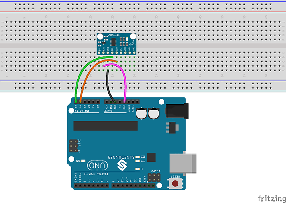
Step1:Connecting circuit
It can share the I2C bus with other I2C devices as long as each device has a unique address. Only 4 connections are required for I2C communication.
- ADXL345 ------- Arduino Uno/Mega2560
- GND --------- GND
- 3.3V ------- 3.3V
- SCL ------- A5 Uno/pin21 Mega2560
- SDA ------- A4 Uno/pin20 Mega2560
- ADXL345 ------- Arduino Uno/Mega2560
#include <Wire.h>
#define Register_ID 0
#define Register_2D 0x2D
#define Register_X0 0x32
#define Register_X1 0x33
#define Register_Y0 0x34
#define Register_Y1 0x35
#define Register_Z0 0x36
#define Register_Z1 0x37
int ADXAddress = 0x53;  //I2C address
int reading = 0;
int val = 0;
int X0,X1,X_out;
int Y0,Y1,Y_out;
int Z1,Z0,Z_out;
double Xg,Yg,Zg;

void setup()
{
  Serial.begin(9600);
  delay(100);
  Wire.begin();
  delay(100);
  Wire.beginTransmission(ADXAddress);
  Wire.write(Register_2D);
  Wire.write(8);
  Wire.endTransmission();
  Serial.println("Accelerometer Test ");
}
void loop()
{
  Wire.beginTransmission(ADXAddress);
  Wire.write(Register_X0);
  Wire.write(Register_X1);
  Wire.endTransmission();
  Wire.requestFrom(ADXAddress,2);
  if(Wire.available()<=2);
  {
    X0 = Wire.read();
    X1 = Wire.read();
    X1 = X1<<8;
    X_out = X0+X1;
  }
  Wire.beginTransmission(ADXAddress);
  Wire.write(Register_Y0);
  Wire.write(Register_Y1);
  Wire.endTransmission();
  Wire.requestFrom(ADXAddress,2);
  if(Wire.available()<=2);
  {
    Y0 = Wire.read();
    Y1 = Wire.read();
    Y1 = Y1<<8;
    Y_out = Y0+Y1;
  }
  Wire.beginTransmission(ADXAddress);
  Wire.write(Register_Z0);
  Wire.write(Register_Z1);
  Wire.endTransmission();
  Wire.requestFrom(ADXAddress,2);
  if(Wire.available()<=2);
  {
    Z0 = Wire.read();
    Z1 = Wire.read();
    Z1 = Z1<<8;
    Z_out = Z0+Z1;
  }
  Xg = X_out/256.00;
  Yg = Y_out/256.00;
  Zg = Z_out/256.00;
  Serial.print("X=");
  Serial.print(Xg);
  Serial.print("\tY=");
  Serial.print(Yg);
  Serial.print("\tZ=");
  Serial.println(Zg);
  delay(300);
}
Step3: Select correct Board and Port
Step4: Upload the sketch to the SunFounder Uno board
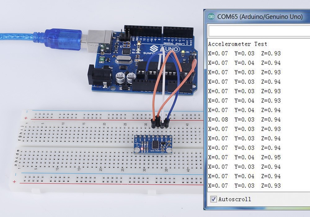
After uploading, open Serial Monitor, where you can see the data detected. When the acceleration of the module changes, the figure will change accordingly on the window.
