Difference between revisions of "FT232RL FTDI Module"
(Created page with "==Premises== In this tutorial, we will use the SunFounder FT232 Serial to TTL and the PuTTy - an SSH and the telnet client. Refer to the website <font color="blue">http://www....") |
(→Pins Functions) |
||
| (8 intermediate revisions by the same user not shown) | |||
| Line 1: | Line 1: | ||
| − | == | + | ==Introduction== |
| + | |||
| + | [[File:FTDI-1.jpg]]<br> | ||
| + | |||
| + | This USB to TTL serial adapter module is compatible with different types of computers and drivers. The power LED, TXD LED and the RXD LED on the module can help detect whether it works normally. The power supply voltage can be selected through toggling the switch. Usually 5V or 3V is allowed. A 500mA self-restore fuse is used for over current protection. The module is also used for general serial applications.<br> | ||
| + | |||
| + | ==Pins Functions== | ||
| + | |||
| + | {|border="1" class="wikitable" | ||
| + | !scope="col" |Pin | ||
| + | !scope="col" |Function | ||
| + | |- | ||
| + | |GND | ||
| + | |connected to ground | ||
| + | |- | ||
| + | |5V | ||
| + | |connected to a +5V power supply | ||
| + | |- | ||
| + | |TXD | ||
| + | |to send signal | ||
| + | |- | ||
| + | |RXD | ||
| + | |to receive signal | ||
| + | |} | ||
| + | |||
| + | ==Functions of the Switch== | ||
| + | |||
| + | [[File:FTDI-2.png]]<br> | ||
| + | |||
| + | The switch is to select the power supply voltage to 5V or 3.3V, representing the voltage between the signal receiving end (RXD) and the sending end (TXD). When you toggle the switch to 3.3V, the voltage between the TXD and RXD will be 3.3V, which fits those 3.3V control boards, such as the Raspberry Pi.<br> | ||
| + | |||
| + | ==How It Works== | ||
| + | '''<font color="orange">Premises</font>'''<br> | ||
In this tutorial, we will use the SunFounder FT232 Serial to TTL and the PuTTy - an SSH and the telnet client. Refer to the website <font color="blue">http://www.putty.org/</font> for more. | In this tutorial, we will use the SunFounder FT232 Serial to TTL and the PuTTy - an SSH and the telnet client. Refer to the website <font color="blue">http://www.putty.org/</font> for more. | ||
Though here we use a Raspberry Pi 2, the tutorial also applies to other Raspberry Pi models. | Though here we use a Raspberry Pi 2, the tutorial also applies to other Raspberry Pi models. | ||
| − | = | + | '''<font color="orange">Procedures</font>'''<br> |
'''Step 1'''. Insert the TF card into the Raspberry Pi, and connect it to power. Connect the FT232 to your computer with a Micro USB cable. Next, connect the FT232 to the Raspberry Pi as shown below. | '''Step 1'''. Insert the TF card into the Raspberry Pi, and connect it to power. Connect the FT232 to your computer with a Micro USB cable. Next, connect the FT232 to the Raspberry Pi as shown below. | ||
Latest revision as of 07:56, 13 June 2017
Introduction
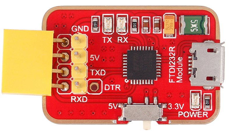
This USB to TTL serial adapter module is compatible with different types of computers and drivers. The power LED, TXD LED and the RXD LED on the module can help detect whether it works normally. The power supply voltage can be selected through toggling the switch. Usually 5V or 3V is allowed. A 500mA self-restore fuse is used for over current protection. The module is also used for general serial applications.
Pins Functions
| Pin | Function |
|---|---|
| GND | connected to ground |
| 5V | connected to a +5V power supply |
| TXD | to send signal |
| RXD | to receive signal |
Functions of the Switch
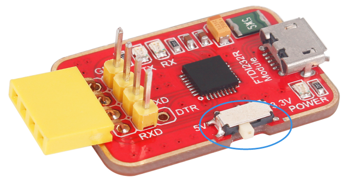
The switch is to select the power supply voltage to 5V or 3.3V, representing the voltage between the signal receiving end (RXD) and the sending end (TXD). When you toggle the switch to 3.3V, the voltage between the TXD and RXD will be 3.3V, which fits those 3.3V control boards, such as the Raspberry Pi.
How It Works
Premises
In this tutorial, we will use the SunFounder FT232 Serial to TTL and the PuTTy - an SSH and the telnet client. Refer to the website http://www.putty.org/ for more.
Though here we use a Raspberry Pi 2, the tutorial also applies to other Raspberry Pi models.
Procedures
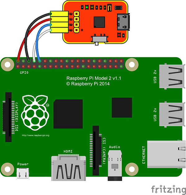
Step 1. Insert the TF card into the Raspberry Pi, and connect it to power. Connect the FT232 to your computer with a Micro USB cable. Next, connect the FT232 to the Raspberry Pi as shown below.
Make sure it is connected to computer correctly.
Step 2. Check the port number in Device Manager of your computer that runs on Windows.
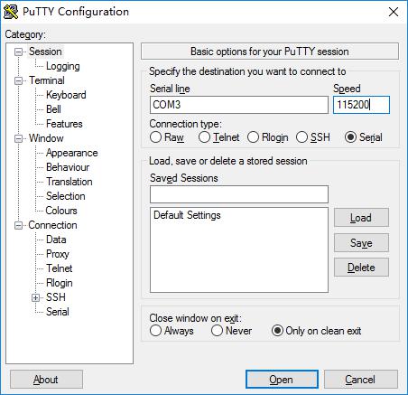
Then open the PuTTy, click Session in the left sidebar. Under Specify the destination you want to connect to, select Serial.
Enter the corresponding port number in Serial Line, and 115200 in Speed.
Step 3. Click Open at the bottom. Then a larger window will pop up.
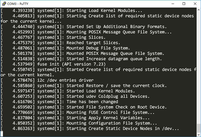
If your Raspberry Pi is booting now, the window will show the corresponding information:
When the booting is completed, a login prompt will pop up.
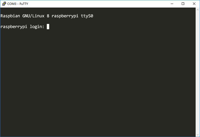
If the Raspberry Pi has been booted already,, no prompt will be shown in the window. Press Enter, and a login prompt will appear:
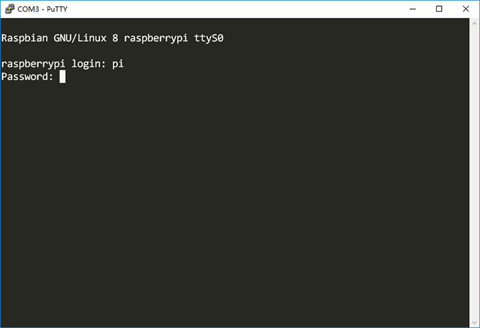
Type in the default Raspbian user name pi, then press Enter:
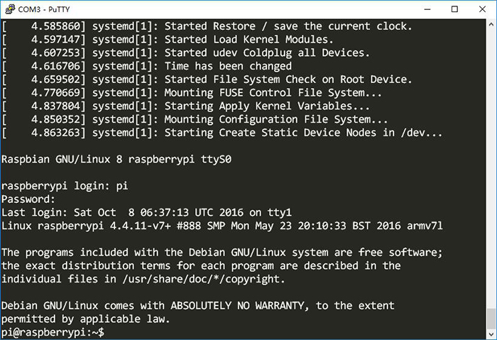
Then type in the password, raspberry. Press Enter again to log in. (Note: when you type in the password, no character will appear on the screen due to the rule of typing in a password under Bash in Linux. Be careful to type in the password correctly.)
Now you have logged in to the Raspberry Pi by serial.
