Difference between revisions of "4 Channel 5V Relay Module"
(Created page with "=='''Introduction'''== This is a 5V 4-channel relay interface board, and each channel needs a 15-20mA driver current. It can be used to control various appliances and equipm...") |
(→Resource) |
||
| (9 intermediate revisions by the same user not shown) | |||
| Line 1: | Line 1: | ||
=='''Introduction'''== | =='''Introduction'''== | ||
| − | + | [[File:6 zpsilyctpb7.jpg]]<br> | |
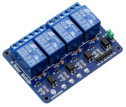
This is a 5V 4-channel relay interface board, and each channel needs a 15-20mA driver current. It can be used to control various appliances and equipment with large current. It is equiped with high-current relays that work under AC250V 10A or DC30V 10A. It has a standard interface that can be controlled directly by microcontroller.<br> | This is a 5V 4-channel relay interface board, and each channel needs a 15-20mA driver current. It can be used to control various appliances and equipment with large current. It is equiped with high-current relays that work under AC250V 10A or DC30V 10A. It has a standard interface that can be controlled directly by microcontroller.<br> | ||
=='''Principle'''== | =='''Principle'''== | ||
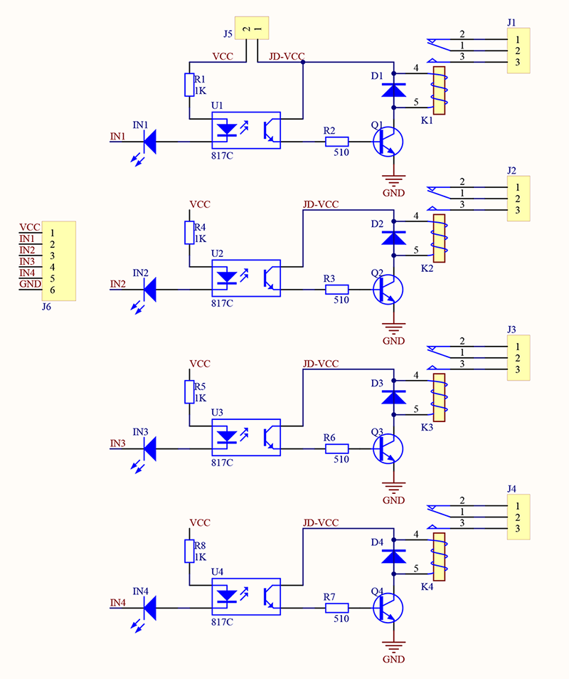
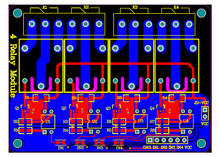
| − | From the picture below, you can see that when the signal port is at low level, the signal light will light up and the optocoupler 817c (it transforms electrical signals by light and can isolate input and output electrical signals) will conduct, and then the transistor will conduct, the relay coil will be electrified, and the normally open contact of the relay will be closed. When the signal port is at high level, the normally closed contact of the relay will be closed. So you can connect and disconnect the load by controlling the level of the control signal port. | + | From the picture below, you can see that when the signal port is at low level, the signal light will light up and the optocoupler 817c (it transforms electrical signals by light and can isolate input and output electrical signals) will conduct, and then the transistor will conduct, the relay coil will be electrified, and the normally open contact of the relay will be closed. When the signal port is at high level, the normally closed contact of the relay will be closed. So you can connect and disconnect the load by controlling the level of the control signal port.<br> |
| − | + | [[File:4 channel relay schematic.png]] | |
| + | [[File:4 channel relay PCB.png]] | ||
| + | |||
=='''Pin Description'''== | =='''Pin Description'''== | ||
===Input:=== | ===Input:=== | ||
| Line 54: | Line 56: | ||
|} | |} | ||
| − | Then upload the code. You should see the relays close one by one and the LED on the board and the LEDs connected to K1 and K2 light up or go out with the relays opened or closed. | + | Then upload the code. You should see the relays close one by one and the LED on the board and the LEDs connected to K1 and K2 light up or go out with the relays opened or closed.<br> |
| − | + | [[File:4 Channels relay0201.png]] | |
===Code=== | ===Code=== | ||
| Line 104: | Line 106: | ||
You can use this 4-channel relay to drive some household appliances, such as table lamp, fan, etc. | You can use this 4-channel relay to drive some household appliances, such as table lamp, fan, etc. | ||
=='''Resource'''== | =='''Resource'''== | ||
| + | [http://wiki.sunfounder.cc/images/1/1f/Relay_datasheet.pdf Relay_datasheet][[File:PDF.jpg]]<br> | ||
| + | [http://wiki.sunfounder.cc/images/1/1c/4_channel_relay_Schematic.pdf 4_channel_relay_Schematic.pdf][[File:PDF.jpg]] | ||
Latest revision as of 06:38, 20 March 2017
Contents
Introduction

This is a 5V 4-channel relay interface board, and each channel needs a 15-20mA driver current. It can be used to control various appliances and equipment with large current. It is equiped with high-current relays that work under AC250V 10A or DC30V 10A. It has a standard interface that can be controlled directly by microcontroller.
Principle
From the picture below, you can see that when the signal port is at low level, the signal light will light up and the optocoupler 817c (it transforms electrical signals by light and can isolate input and output electrical signals) will conduct, and then the transistor will conduct, the relay coil will be electrified, and the normally open contact of the relay will be closed. When the signal port is at high level, the normally closed contact of the relay will be closed. So you can connect and disconnect the load by controlling the level of the control signal port.


Pin Description
Input:
VCC: Positive supply voltage
GND: Ground
IN1--IN4: Relay control port
Output:
Connect a load, DC 30V/10A,AC 250V/10A
Features:
- Size: 75mm (Length) * 55mm (Width) * 19.3mm (Height)
- Weight: 61g
- PCB Color: Blue
- There are four fixed screw holes at each corner of the board, easy for install and fix. The diameter of the hole is 3.1mm
- High quality Songle relay is used with single pole double throw, a common terminal, a normally open terminal, and a normally closed terminal
- Optical coupling isolation, good anti-interference.
- Closed at low level with indicator on, released at high level with indicator off
- VCC is system power source, and JD_VCC is relay power source. Ship 5V relay by default. Plug jumper cap to use
- The maximum output of the relay: DC 30V/10A, AC 250V/10A
Testing Experiment
Experiment Principle
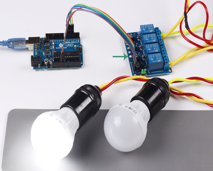
When the input terminals (IN1, IN2, IN3, IN4) are supplied with low level signals, you can see relay K1, K2, K3, K4 closed successively and repeat this cycle. In order to show its the ability of driving load more intuitively, two LEDs are connected to relay K1 and K2.
Experiment Steps
Build the circuit
| 4 Channel relay shield | SunFounder uno R3 |
|---|---|
| GND | GND |
| IN1 | 3 |
| IN2 | 4 |
| IN3 | 5 |
| IN4 | 6 |
| VCC | 5V |
Then upload the code. You should see the relays close one by one and the LED on the board and the LEDs connected to K1 and K2 light up or go out with the relays opened or closed.

Code
//the relays connect to
int IN1 = 3;
int IN2 = 4;
int IN3 = 5;
int IN4 = 6;
#define ON   0
#define OFF  1
void setup()
{
  relay_init();//initialize the relay
}

void loop() {

  relay_SetStatus(ON, OFF, OFF,OFF);//turn on RELAY_1
  delay(2000);//delay 2s
  relay_SetStatus(OFF, ON, OFF,OFF);//turn on RELAY_2
  delay(2000);//delay 2s
  relay_SetStatus(OFF, OFF, ON,OFF);//turn on RELAY_3
  delay(2000);//delay 2s
  relay_SetStatus(OFF, OFF, OFF,ON);//turn on RELAY_3
  delay(2000);//delay 2s
}
void relay_init(void)//initialize the relay
{
  //set all the relays OUTPUT
  pinMode(IN1, OUTPUT);
  pinMode(IN2, OUTPUT);
  pinMode(IN3, OUTPUT);
  pinMode(IN4, OUTPUT);
  relay_SetStatus(OFF,OFF,OFF,OFF);//turn off all the relay
}
//set the status of relays
void relay_SetStatus( unsigned char status_1,  unsigned char status_2, unsigned char status_3,unsigned char status_4)
{
  digitalWrite(IN1, status_1);
  digitalWrite(IN2, status_2);
  digitalWrite(IN3, status_3);
  digitalWrite(IN4, status_4);

}
Summary
You can use this 4-channel relay to drive some household appliances, such as table lamp, fan, etc.