Difference between revisions of "LCD1602 Module"
(→The Experiment for Raspberry Pi) |
|||
| (34 intermediate revisions by the same user not shown) | |||
| Line 1: | Line 1: | ||
==Introduction== | ==Introduction== | ||
| − | LCD1602, or 1602 character-type liquid crystal display, is a kind of dot matrix module to show letters, numbers, and characters and so on. It's composed of 5x7 or 5x11 dot matrix positions; each position can display one character. There's a dot pitch between two characters and a space between lines, thus separating characters and lines. The | + | |
| + | [[File:lcd1602-1.jpg]]<br> | ||
| + | |||
| + | LCD1602, or 1602 character-type liquid crystal display, is a kind of dot matrix module to show letters, numbers, and characters and so on. It's composed of 5x7 or 5x11 dot matrix positions; each position can display one character. There's a dot pitch between two characters and a space between lines, thus separating characters and lines. The model 1602 means it displays 2 lines of 16 characters.<br> | ||
Generally, LCD1602 has parallel ports, that is, it would control several pins at the same time. LCD1602 can be categorized into eight-port and four-port connections. If the eight-port connection is used, then all the digital ports of the SunFounder Uno board are almost completely occupied. If you want to connect more sensors, there will be no ports available. Therefore, the four-port connection is used here for better application.<br> | Generally, LCD1602 has parallel ports, that is, it would control several pins at the same time. LCD1602 can be categorized into eight-port and four-port connections. If the eight-port connection is used, then all the digital ports of the SunFounder Uno board are almost completely occupied. If you want to connect more sensors, there will be no ports available. Therefore, the four-port connection is used here for better application.<br> | ||
| − | + | ==Pins Functions== | |
| − | + | [[File:lcd1602-2.jpg]]<br> | |
| − | + | ||
| − | + | ==The Experiment for Arduino== | |
| − | + | ||
| − | + | '''<font color="green">Components</font><br> | |
| − | + | - 1 * SunFounder Uno Board<br> | |
| − | + | ||
| − | + | ||
| − | + | ||
| − | + | ||
| − | - 1 * SunFounder Uno | + | |
- 1 * Breadboard<br> | - 1 * Breadboard<br> | ||
- 1 * LCD1602<br> | - 1 * LCD1602<br> | ||
- 1 * Potentiometer (50kΩ)<br> | - 1 * Potentiometer (50kΩ)<br> | ||
| − | - 1 * USB | + | - 1 * USB Cable<br> |
| − | - Jumper | + | - Several Jumper Wires<br> |
| − | = | + | |
| − | + | ||
| − | + | '''<font color="green">Experimental Procedures</font><br> | |
| − | ''<font color=" | + | <font color="red">Note: Before connecting circuit, need to plug the pin headers onto a breadboard, and then put the LCD1602 on to it for easy soldering.</font><br> |
| + | |||
| + | [[File:lcd1602-3-3.jpg]]<br> | ||
| + | |||
| + | '''Step 1:''' Build the circuit (make sure the pins are connected correctly. Otherwise, characters will not be displayed properly):<br> | ||
| + | |||
| + | [[File:Lcd1602-4.jpg.png]]<br> | ||
| + | |||
| + | '''Step 2:''' Download the package [http://wiki.sunfounder.cc/images/b/b2/LCD1602_for_Arduino.rar LCD1602_for_Arduino], then unzip it and open the LCD1602.ino file<br> | ||
| + | |||
| + | [[File:Lcd1602-5.jpg.png]]<br> | ||
| + | |||
| + | '''Step 3:''' Select correct Board and Port<br> | ||
| + | '''Step 4:''' Upload the sketch to the SunFounder Uno board<br> | ||
| + | |||
| + | |||
| + | '''<font color="green">Experimental Phenomenon</font><br> | ||
| + | <font color="red">Note: You may need to adjust the potentiometer on the LCD1602 until it can display clearly.</font><br> | ||
| + | You should now see the characters "SunFounder" and "hello, world! " rolling on the LCD.<br> | ||
| + | |||
| + | [[File:lcd1602-6.jpg]]<br> | ||
| + | |||
| + | ==The Experiment for Raspberry Pi== | ||
| + | |||
| + | '''<font color="green">Components</font><br> | ||
| + | - 1 * Raspberry Pi<br> | ||
| + | - 1 * Breadboard<br> | ||
| + | - 1 * LCD1602<br> | ||
| + | - 1 * Potentiometer<br> | ||
| + | - Several Jumper Wires<br> | ||
| + | |||
| + | |||
| + | '''<font color="green">Experimental Procedures</font><br> | ||
| + | '''Step 1:''' Build the circuit (please be sure the pins are connected correctly. Otherwise, characters will not be displayed properly):<br> | ||
| + | |||
| + | {| border="1" class="wikitable" | ||
| + | |- | ||
| + | ! scope="col" | LCD1602/2004 | ||
| + | ! scope="col" | SunFounder Uno board | ||
| + | |- | ||
| + | |align="center"|K | ||
| + | |align="center"|GND | ||
| + | |- | ||
| + | |align="center"|A | ||
| + | |align="center"|3.3V | ||
| + | |- | ||
| + | |align="center"|D7 | ||
| + | |align="center"|GPIO18 | ||
| + | |- | ||
| + | |align="center"|D6 | ||
| + | |align="center"|GPIO23 | ||
| + | |- | ||
| + | |align="center"|D5 | ||
| + | |align="center"|GPIO24 | ||
| + | |- | ||
| + | |align="center"|D4 | ||
| + | |align="center"|GPIO25 | ||
| + | |- | ||
| + | |align="center"|D0-D3 | ||
| + | |align="center"|No Connected | ||
| + | |- | ||
| + | |align="center"|E | ||
| + | |align="center"|GPIO22 | ||
| + | |- | ||
| + | |align="center"|R/W | ||
| + | |align="center"|GND | ||
| + | |- | ||
| + | |align="center"|RS | ||
| + | |align="center"|GPIO27 | ||
| + | |- | ||
| + | |align="center"|OV | ||
| + | |align="center"|Connect to the middle pin of potentiometer | ||
| + | |- | ||
| + | |align="center"|VDD | ||
| + | |align="center"|5V | ||
| + | |- | ||
| + | |align="center"|VSS | ||
| + | |align="center"|GND | ||
| + | |- | ||
| + | |} | ||
| + | |||
| + | [[File:Lcd1602-8.jpg.png]]<br> | ||
| + | |||
| + | <font color="red">Note: After you run the code, characters may not appear on the LCD1602. You need to adjust the contrast of the screen (the gradual change from black to white) by spinning the potentiometer clockwise or anticlockwise, until the screen displays characters clearly.</font><br> | ||
| + | |||
| + | '''Step 2:''' Transfer the package [http://wiki.sunfounder.cc/images/8/87/LCD1602_for_Raspberry_Pi.zip LCD1602_for_Raspberry_Pi] to the Raspberry Pi<br> | ||
| + | <pre> | ||
| + | wget http://wiki.sunfounder.cc/images/8/87/LCD1602_for_Raspberry_Pi.zip | ||
| + | </pre> | ||
| + | |||
| + | '''Step 3:''' Extract the package<br> | ||
| + | <pre> | ||
| + | unzip LCD1602_for_Raspberry_Pi.zip | ||
| + | </pre> | ||
| + | |||
| + | '''<font color="orange">(For C Language Users)</font><br> | ||
| + | '''Step 4:''' Get into the folder of code<br> | ||
| + | <pre> | ||
| + | cd LCD1602_for_Raspberry_Pi/C | ||
| + | </pre> | ||
| + | |||
| + | '''Step 5:''' Compile<br> | ||
| + | <pre> | ||
| + | gcc lcd1602.c –o lcd1602 –lwiringPiDev –lwiringPi | ||
| + | </pre> | ||
| + | |||
| + | '''Step 6:''' Run<br> | ||
| + | <pre> | ||
| + | sudo ./lcd1602 | ||
| + | </pre> | ||
| − | + | '''<font color="orange">(For Python Users)</font><br> | |
| + | '''Step 4:''' Get into the folder of code<br> | ||
| + | <pre> | ||
| + | cd LCD1602_for_Raspberry_Pi/Python | ||
| + | </pre> | ||
| − | Step | + | '''Step 5:''' Run<br> |
| + | <pre> | ||
| + | sudo python lcd1602.py | ||
| + | </pre> | ||
| − | |||
| − | + | '''<font color="green">Experimental Phenomenon</font><br> | |
| − | + | You should see two lines of characters displayed on the LCD1602: “hello, world! ” , “SunFounder”.<br> | |
| − | + | ||
| − | ''<font color=" | + | [[File:lcd1602-9.jpg]]<br> |
| − | + | ||
| − | You should | + | |
| − | [[File: | + | ==Resource== |
| + | [http://wiki.sunfounder.cc/images/b/b2/LCD1602_for_Arduino.rar LCD1602_for_Arduino][[File:ZIP.jpg]]<br> | ||
| + | [http://wiki.sunfounder.cc/images/8/87/LCD1602_for_Raspberry_Pi.zip LCD1602_for_Raspberry_Pi][[File:ZIP.jpg]]<br> | ||
Latest revision as of 03:33, 7 March 2018
Contents
Introduction
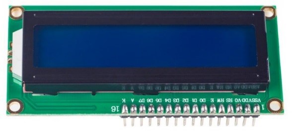
LCD1602, or 1602 character-type liquid crystal display, is a kind of dot matrix module to show letters, numbers, and characters and so on. It's composed of 5x7 or 5x11 dot matrix positions; each position can display one character. There's a dot pitch between two characters and a space between lines, thus separating characters and lines. The model 1602 means it displays 2 lines of 16 characters.
Generally, LCD1602 has parallel ports, that is, it would control several pins at the same time. LCD1602 can be categorized into eight-port and four-port connections. If the eight-port connection is used, then all the digital ports of the SunFounder Uno board are almost completely occupied. If you want to connect more sensors, there will be no ports available. Therefore, the four-port connection is used here for better application.
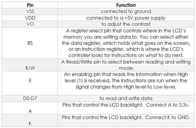
Pins Functions
The Experiment for Arduino
Components
- 1 * SunFounder Uno Board
- 1 * Breadboard
- 1 * LCD1602
- 1 * Potentiometer (50kΩ)
- 1 * USB Cable
- Several Jumper Wires
Experimental Procedures
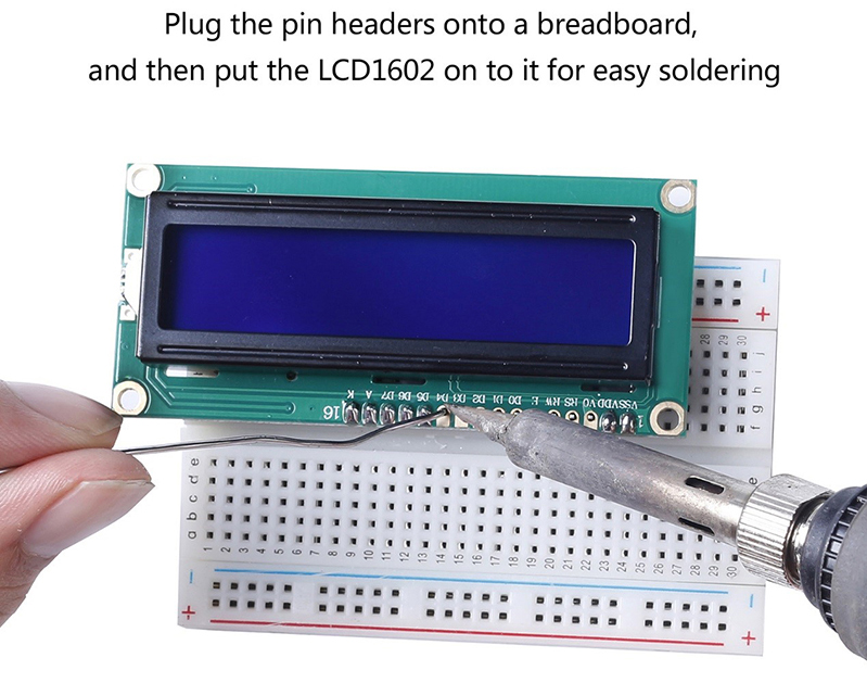
Note: Before connecting circuit, need to plug the pin headers onto a breadboard, and then put the LCD1602 on to it for easy soldering.
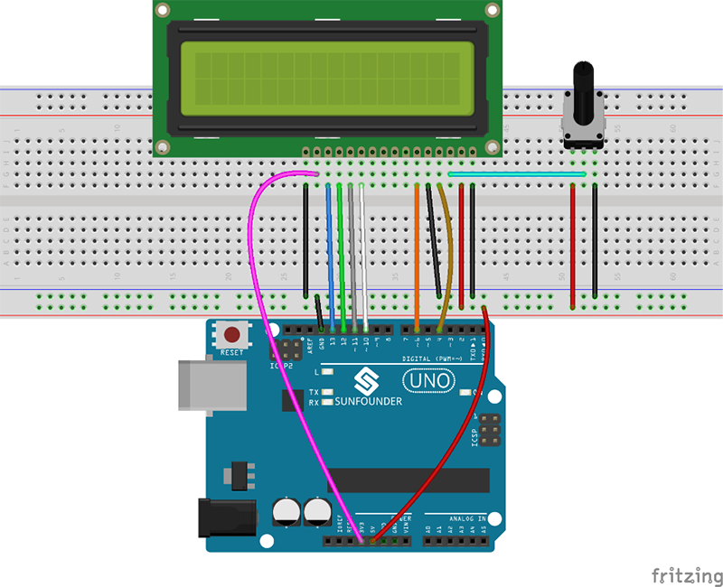
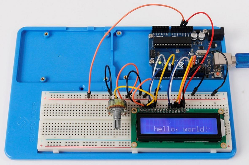
Step 1: Build the circuit (make sure the pins are connected correctly. Otherwise, characters will not be displayed properly):
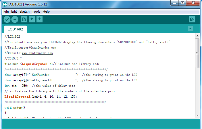
Step 2: Download the package LCD1602_for_Arduino, then unzip it and open the LCD1602.ino file
Step 3: Select correct Board and Port
Step 4: Upload the sketch to the SunFounder Uno board
Experimental Phenomenon
Note: You may need to adjust the potentiometer on the LCD1602 until it can display clearly.
You should now see the characters "SunFounder" and "hello, world! " rolling on the LCD.
The Experiment for Raspberry Pi
Components
- 1 * Raspberry Pi
- 1 * Breadboard
- 1 * LCD1602
- 1 * Potentiometer
- Several Jumper Wires
Experimental Procedures
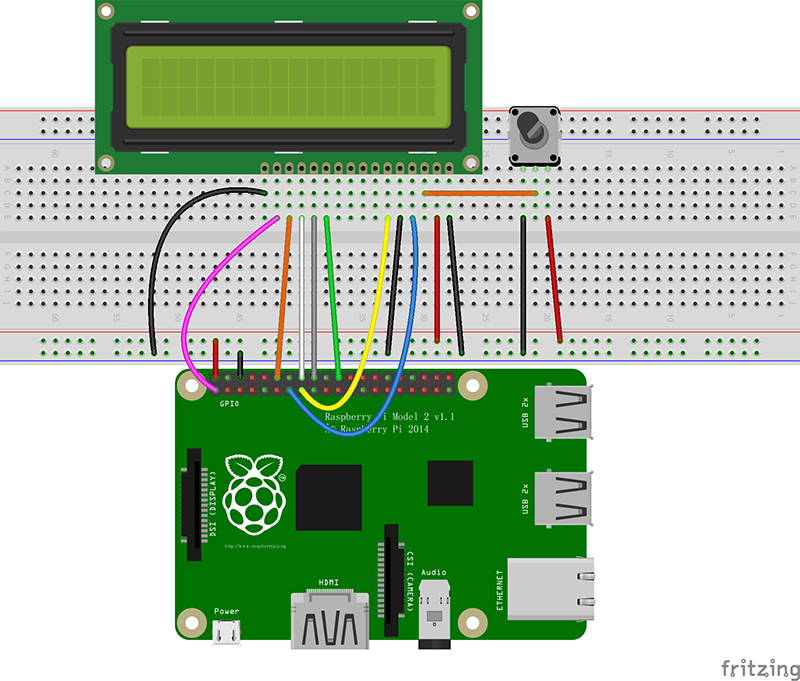
Step 1: Build the circuit (please be sure the pins are connected correctly. Otherwise, characters will not be displayed properly):
| LCD1602/2004 | SunFounder Uno board |
|---|---|
| K | GND |
| A | 3.3V |
| D7 | GPIO18 |
| D6 | GPIO23 |
| D5 | GPIO24 |
| D4 | GPIO25 |
| D0-D3 | No Connected |
| E | GPIO22 |
| R/W | GND |
| RS | GPIO27 |
| OV | Connect to the middle pin of potentiometer |
| VDD | 5V |
| VSS | GND |
Note: After you run the code, characters may not appear on the LCD1602. You need to adjust the contrast of the screen (the gradual change from black to white) by spinning the potentiometer clockwise or anticlockwise, until the screen displays characters clearly.
Step 2: Transfer the package LCD1602_for_Raspberry_Pi to the Raspberry Pi
wget http://wiki.sunfounder.cc/images/8/87/LCD1602_for_Raspberry_Pi.zip
Step 3: Extract the package
unzip LCD1602_for_Raspberry_Pi.zip
(For C Language Users)
Step 4: Get into the folder of code
cd LCD1602_for_Raspberry_Pi/C
Step 5: Compile
gcc lcd1602.c –o lcd1602 –lwiringPiDev –lwiringPi
Step 6: Run
sudo ./lcd1602
(For Python Users)
Step 4: Get into the folder of code
cd LCD1602_for_Raspberry_Pi/Python
Step 5: Run
sudo python lcd1602.py
Experimental Phenomenon
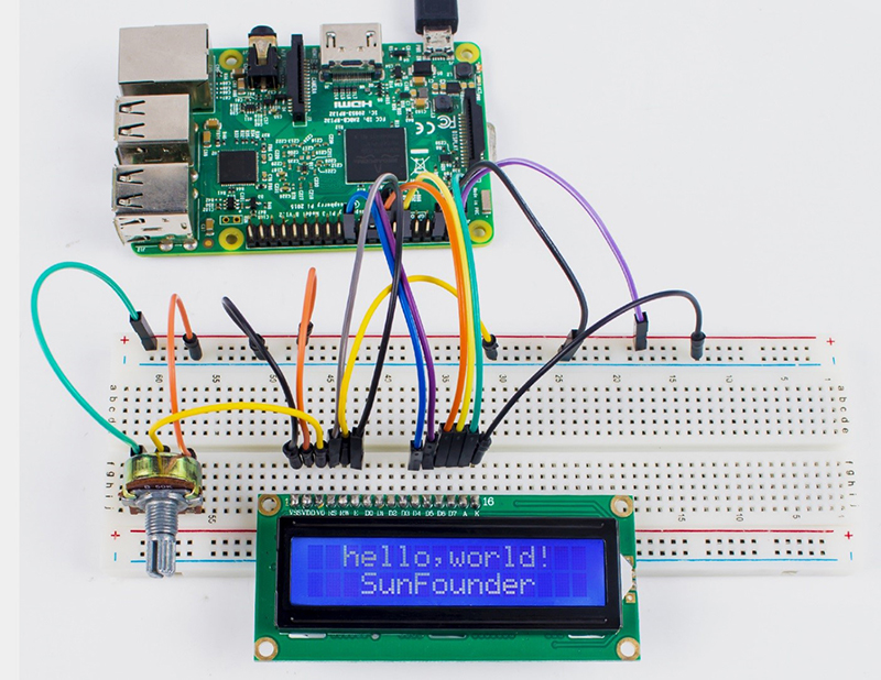
You should see two lines of characters displayed on the LCD1602: “hello, world! ” , “SunFounder”.
