Difference between revisions of "SunFounder 250+Radiolink T8FB Remote Controller(Assembled)"
(→Related links) |
(→4. Assembled Kit Test) |
||
| (44 intermediate revisions by the same user not shown) | |||
| Line 10: | Line 10: | ||
4. Weight: 519g ; Duration of flight: 7 minutes;Working voltage: 11.1V<br> | 4. Weight: 519g ; Duration of flight: 7 minutes;Working voltage: 11.1V<br> | ||
5. CC3D software debugging guide and Radiolink T8FB Remote Controller are provided for you.<br> | 5. CC3D software debugging guide and Radiolink T8FB Remote Controller are provided for you.<br> | ||
| − | + | Prior to flying the plane, you need to know more about the plane and flight. Please read the following instructions carefully and make sure you understand well before actual flight.<br> | |
| − | Prior to flying the plane, you need to know more about the plane and flight. Please read the following instructions carefully and make sure you understand well before actual flight. | + | |
| − | + | ||
| − | + | ||
| − | + | =='''Components Test Before Assembly'''== | |
| + | Please check whether the components on the list are damaged or missing. Remember to test the components like battery, power indicator alarm, etc., before assembly. If everything works fine, then we can start the test for assembled kit.<br> | ||
| + | ===1. Battery, Balance Charger and Power Adapter Test=== | ||
| − | + | [[File:Rr5.png]]<br> | |
| − | + | '''Test Operations:'''<br> | |
| + | 1. Connect the PR301 Li-ion Polymer Balance Charger (Power Charger) and 12V 1.5A Power Adapter, and plug the adapter to a socket. The power indicator on the balance charger will flash green, while the charging indicator orange (as shown in '''Figure 1-1'''). The charging indicator will dim one second later (as shown in '''Figure 1-2'''), meaning the connection works fine.<br> | ||
| − | ''' | + | [[File:ps1-1-1.png]][[File:ps1-2-2.png]]<br> |
| + | '''Figure 1-1 & Figure 1-2'''<br> | ||
| − | + | 2. Connect the low-power 3S 11.1V 1300m AH T-Plug Li-Po Battery or High Discharge Lithium Polymer Battery(3-cell Li-Polymeter Battery) to the balance charger (DO NOT connect two or three batteries to charger at the same time); Then the charging indicator lights up in red ('''Figure 1-3'''), indicating it’s charging.<br> | |
| − | ''' | + | [[File:ps1-3-3.png]]<br> |
| + | '''Figure 1-3'''<br> | ||
| − | + | 3. When the charging indicator turns from red to green (Figure 1-4), it means the battery is fully charged.<br> | |
| − | + | [[File:ps1-4-4.png]]<br> | |
| + | '''Figure 1-4'''<br> | ||
| − | + | '''Note:'''<br> | |
| + | 1. When you connect the balance charger to power, if the power indicator does not light up, it shows the charger is not well connected to power.<br> | ||
| + | 2. If the charging indicator does not light up after you connect the battery to charger, please check the connection, and whether the battery’s voltage is too low (<1.5V/CELL); If a cell is lower than 3V, the charger will provide low current recovery charging for 3 minutes; if it fails, the charging indicator will blink 0.5 seconds, indicating the battery is damaged. Only when each of all the cells reaches 3V, it will turn to normal charging. The charging indicator will light up green when the battery is fully charged. Please take out the battery in time to avoid battery deformation or even explosion caused by overcharging.<br> | ||
| + | 3. The battery may fail to be charged because of over discharging, thus remember to mount a battery indicator alarm. When an alarm beeping is heard, please take out the battery to charge in time! You can try to recover the damaged battery if you have a stabilizator. Here’s how to do: <br> | ||
| + | 1) Adjust the output voltage to 12.6V as shown in '''Figure 1-5'''; | ||
| − | + | [[File:x9.png]]<br> | |
| + | '''Figure 1-5'''<br> | ||
| − | + | 2) Connect the anode and cathode of the stabilizator directely, and adjust the current to 1A ('''Figure 1-6'''); <br> | |
| − | ''' | + | [[File:x10.png]]<br> |
| + | '''Figure 1-6'''<br> | ||
| − | + | 3) TURN OFF the stabilzator, then connect the anode and cathode of the device to those of the battery ('''Figure 1-7''') - use two wires with different length to distinguish from each other so as to avoid short circuit by careless operation; <br> | |
| − | + | [[File:x11.png]]<br> | |
| + | '''Figure 1-7'''<br> | ||
| − | + | 4) Turn on the device to start the recovery. When the output current changes to 0 or almost 0, the recovery is done as shown in '''Figure 1-8'''.<br> | |
| − | + | [[File:x12.png]]<br> | |
| + | '''Figure 1-8'''<br> | ||
| − | + | ===2. Battery Indicator Alarm (with Buzzer) Test=== | |
| − | + | [[File:x13.png]]<br> | |
| − | + | '''Test Operations:'''<br> | |
| + | 1. Check the back of the Battery Indicator alarm, find the cathode pin marked with “-” (① of Figure 2-1).<br> | ||
| + | 2. Connect the cathode of the Alarm to the first cathode hole of the battery charging cord and the rest pins to the corresponding headers as shown in Figure 2-2.<br> | ||
| + | 3. If they are connected correctly, the alarm will beep for three times, and then it will display the total voltage of all the cells and the voltage of each cell, in cycle.<br> | ||
| + | 4. The warning voltage threshold can be set by the button on the back of the alarm as shown in ② of Figure 2-1. Each press will add 0.1V and the setting will be saved automatically. The threshold value can be set to OFF (turn off alarm), or from 2.7V (default after manufactured) – 3.8V. You are recommended to set it to 3.7V.<br> | ||
| − | + | [[File:x14.png]]<br> | |
| + | '''Figure 2-1'''<br> | ||
| + | <br> | ||
| + | [[File:ps2-2-2.png]]<br> | ||
| + | '''Figure 2-2'''<br> | ||
| − | + | ===3. Power on Radio Transmitter=== | |
| − | + | [[File:x16.png]][[File:x4.png]]<br> | |
| − | + | Power on Radio Transmitter: Connect the High Discharge Lithium Polymer Battery to the transmitter as shown in '''Figure3-1''', then insert it in and put the battery cover back (as shown in '''Figure 3-2''').<br> | |
| − | ''' | + | [[File:x18.png]][[File:x19.png]]<br> |
| + | '''Figure3-1 & Figure3-2'''<br> | ||
| − | + | ===4. Assembled Kit Test=== | |
| + | '''For this assembled kit, you may still need to mount the propellers, battery and battery indicator alarm before flying it. <font color="red">For security reasons, DO NOT mount the propellers in this step to prevent accidents in later test.</font>'''<br> | ||
| + | 1. Cut the velcro tape into halves, each slightly shorter than the battery, and paste the two pieces on the center of the frame and the back of the battery separately (as shown in '''Figure 4-1'''); place the battery on the velcro tape area of the frame, and fix it with a battery strap (as shown in '''Figure 4-2''').<br> | ||
| − | + | [[File:x20-20.jpg]][[File:x21-21.jpg]]<br> | |
| + | '''Figure 4-1 & Figure 4-2'''<br> | ||
| − | + | 2. Mount the battery indicator alarm to the battery: align the pins and headers to mount the alarm as shown in '''Figure 4-3''', and fix it on the frame with nylon ties.<br> | |
| − | + | [[File:x22.jpg]]<br> | |
| + | '''Figure 4-3'''<br> | ||
| − | + | 3. Turn on the transmitter ('''Figure 4-4'''). Then power on the aircraft: connect the power cord on the plane with that of the battery ('''Figure 4-5''').<br> | |
| − | + | [[File:x23.jpg]][[File:x24.png]]<br> | |
| + | '''Figure 4-4 & Figure 4-5'''<br> | ||
| − | + | 4. Pull the Throttle stick to the bottom and then rightmost (as shown in Figure 4-6), and you can see the blue light on the flight controller blinks. Keep this status for 3 seconds; when the blinking slows down, release the Throttle. Now the aircraft is unlocked successfully.<br> | |
| − | ''' | + | [[File:x25-25-25.jpg]][[File:x26-26.png]]<br> |
| + | '''Figure 4-6'''<br> | ||
| − | + | 5. Pull the Throttle upward slightly (Figure 4-7), and you can see the motor starts to spin. <font color="red">Note: If you have mounted the propellers unconsciously, DO NOT pull the Throttle stick rapidly, because it’s very DANGEROUS!!!</font><br> | |
| − | ''' | + | [[File:x27-27-27.jpg]][[File:x28-28.jpg]]<br> |
| + | '''Figure 4-7'''<br> | ||
| − | + | 6. Pull the Throttle to the bottom and then leftmost (Figure 4-8), and keep for 3 seconds; when the blue light’s blinking slows down, release it. Then the aircraft is locked.<br> | |
| + | |||
| + | [[File:x29-29.jpg]][[File:x26-26.png]]<br> | ||
| + | '''Figure 4-8'''<br> | ||
| + | |||
| + | ===5. Trial Flight=== | ||
| + | '''If all previous tests work fine, just mount the propellers to start the trial flight.'''<br> | ||
| + | 1. There are two types propellers: CW propeller ('''Figure 5-1''') and CCW propeller (as shown in '''Figure 5-2'''). Remember to distinguish the propeller types and mount them as shown in '''Figure 5-3''', with the CW props at No. 1 & 3 and CCW ones at 2 & 4, then fix them with black or white bullet caps separately.<br> | ||
| + | |||
| + | [[File:x31.jpg]][[File:x32.jpg]]<br> | ||
| + | '''Figure 5-1 & Figure 5-2'''<br> | ||
| + | [[File:x33.jpg]]<br> | ||
| + | '''Figure 5-3''' | ||
| + | |||
| + | 2. During the trial flight, you may encounter some problems. For example, the aircraft may tilt to a certain direction in the flight. If so, you need to connect the flight controller to computer for debugging. For more details, please check the instruction manual – '''CC3D Software Debugging.'''<br> | ||
| + | |||
| + | |||
| + | =='''Calibration after flight'''== | ||
| + | In the flight previously, you may encounter some problems. For example, the plane keeps tilting toward a certain direction. It may be changed parameter for the plane during the shipment. Take the following steps to calibrate. <br> | ||
| + | 1) Calibrate the radio transmitter <br> | ||
| + | Remove the propellers from the aircraft, connect the flight controller to the computer with a USB cable. Open the Openpilot and click Iuput.<br> | ||
| + | Pull the trimmer toggle for Pitch, Yaw, and Roll, as shown below. <br> | ||
| + | |||
| + | [[File:Fegr.png]]<br> | ||
| + | |||
| + | Adjust them until the median is about 1500, click Save. <br> | ||
| + | |||
| + | [[File:1356.png]]<br> | ||
| + | |||
| + | 2) Make sure the flight mode channel is pulled to Stabilized1 (self-stabilization)<br> | ||
| + | Click Flight Mode Switch Settings. <br> | ||
| + | |||
| + | '''Stabilized1''': self-stabilization mode - then Roll, Pitch and Yaw are all under the self-stabilization mode.<br> | ||
| + | '''Stabilized2''': semi-self-stabilization mode - Roll and Pitch are self-stabilization when Yaw is still manual.<br> | ||
| + | '''Stabilized3''': manual mode - Roll, Pitch and Yaw are all under the manual mode.<br> | ||
| + | |||
| + | [[File:12edcf.jpg]]<br> | ||
| + | |||
| + | Pull the assistant channel at the right upper corner of the radio transmitter to check the gear corresponding to the flight mode (self-stabilization, semi-self-stabilization, and manual mode).<br> | ||
| + | |||
| + | [[File:Regser.png]]<br> | ||
| + | |||
| + | For example, pull it to the highest, and it is Stabilized1.<br> | ||
| + | |||
| + | [[File:Bsdfbs.png]] | ||
| + | |||
| + | 3) Click FlightData to check whether the level line overlaps the yellow line. If yes, it means the calibration is done well; but if not, please move on to the following steps. <br> | ||
| + | |||
| + | [[File:Gbvsdfgf.png]] <br> | ||
| + | |||
| + | 4) Place the plane on a level surface, click Altitude and then Level for the horizontal calibration. After it's done 100%, click Save. <br> | ||
| + | |||
| + | [[File:Fg v.png]] <br> | ||
| + | |||
| + | Click Flight Data again and you should see the lines overlapped. <br> | ||
| + | |||
| + | [[File:Bfds.png]]<br> | ||
| + | |||
| + | So you've finished the debugging. Now assemble back the propellers to the plane, unlock it, and check whether the drone can fly steadily now. <br> | ||
| + | Note: During the flight, if a crash happens unluckily, the parameters for the plane may change. DO calibrate it again based on the instructions above.<br> | ||
=='''Related links'''== | =='''Related links'''== | ||
| − | 1. | + | 1.Downlaod the the Ground Control Station (GCS) for the CC3D flight controller board: |
| − | Windows:<font color="blue">''' | + | Windows:<font color="blue">'''http://wiki.sunfounder.cc/images/3/32/OpenPilot-RELEASE-15.02.02-win32.rar'''</font><br> |
| − | Mac OS X:<font color="blue">''' | + | Mac OS X:<font color="blue">'''http://wiki.sunfounder.cc/images/6/69/Openpilot-release-13.06.04-osx.rar'''</font><br> |
| + | |||
| + | '''Note:OPENPILOT WAS DISCONTINUED!'''<br> | ||
| + | |||
| + | Use '''LibrePilot''' instead.<br> | ||
| + | For the latest version of LibrePilot, you can go here to download:<br> | ||
| + | http://opwiki.readthedocs.io/en/latest/user_manual/gcs_install_lp.html<br> | ||
| + | |||
| + | 2. For the assembling videos, please refer to this link: | ||
| + | |||
| + | <font color="blue">'''https://www.youtube.com/watch?v=-YJQD8M1F0s'''</font> | ||
| + | |||
| + | |||
| + | 3.The SunFoundere 250 quadcopter kit uses the 5045 propellers blades. you can also choose other 50x propellers blades : | ||
| + | |||
| + | <font color="blue">'''https://www.sunfounder.com/drone/propellers/5030propeller.html'''</font><br> | ||
| + | <font color="blue">'''https://www.sunfounder.com/drone/propellers/5045propeller.html'''</font><br> | ||
| + | <font color="blue">'''https://www.sunfounder.com/drone/propellers/3-blade.html'''</font><br> | ||
| + | |||
| + | 4.For the camera kit, you are recommended to refer to this link: | ||
| + | |||
| + | <font color="blue">'''https://www.sunfounder.com/drone/flight-camera/minicamera.html'''</font><br> | ||
| + | <font color="blue">'''https://www.sunfounder.com/drone/fpv-image-transceiver-kit-with-700tvl-hd-camera-mini-ts5823-32-channel-av-transmitter-5-8g-mushroom-antenna-for-quadcopter-multirotor-aircraft.html'''</font> | ||
| + | |||
| + | 5. For the FPV TFT LCD, you are recommended to refer to this link: | ||
| − | + | <font color="blue">'''https://www.sunfounder.com/drone/fpv-lcd.html'''</font> | |
| − | + | 6. For the FPV Image Transceiver Kit, you are recommended to refer to this link: | |
| − | <font color="blue">'''https://www.sunfounder.com/drone/ | + | <font color="blue">'''https://www.sunfounder.com/drone/fpv-image-transceiver-kit-with-700tvl-hd-camera-mini-ts5823-32-channel-av-transmitter-5-8g-mushroom-antenna-for-quadcopter-multirotor-aircraft.html'''</font> |
Latest revision as of 03:33, 7 August 2017
Contents
Introduction
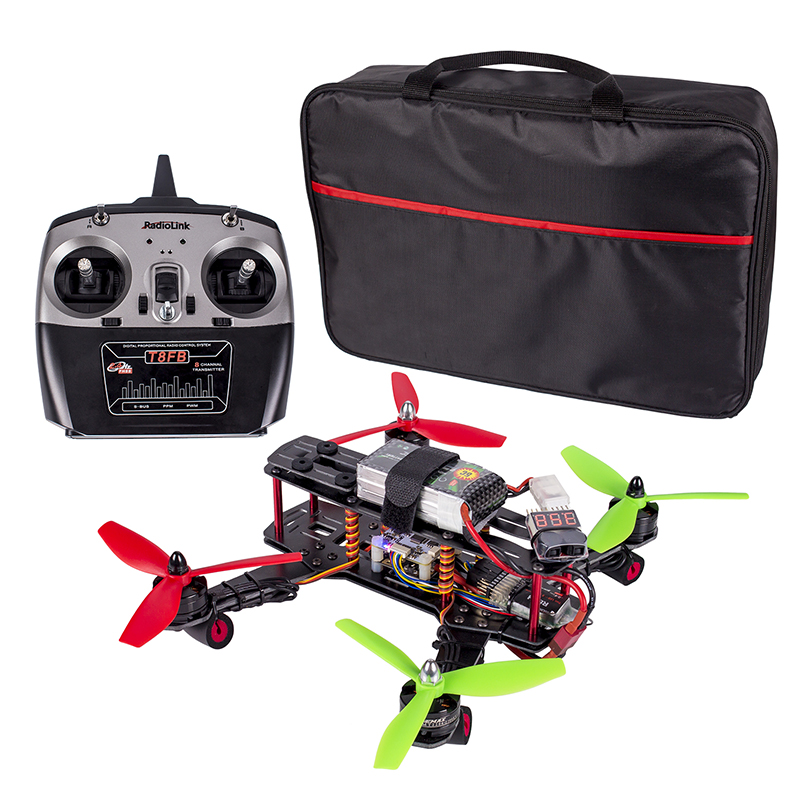
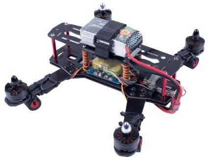
The SunFounder 250 Quadcopter is tailored for the hobbyists for FPV flying.The racing drone is designed for pursuing the fast speed, which is totally different from those UVA drones who can provide extremely stable flying.you can fly it immediately when you get it.
If you purchase it, you will be issued together with attractive packaging. It features stability, flexibility and activity. Mini Design, EMAX motors with 5045 plastic propeller give SunFounder 250 racing quadcopter more powers.Pushing the throttle, you will feel the fast reaction of the drone. You can realize a stable flight in a high or low altitude or in a forest with the SunFounder 250.
Features
1. Pre-assembled the SunFounder 250 quadcopter and tested it before shipping it out, ready to fly.
2. Full glass fiber frame kit, ultralight and great intensity.
3. It runs the firmware of CC3D flight controller(well calibrated), working with the EMAX Simon 12A brushless motor and ESC.
4. Weight: 519g ; Duration of flight: 7 minutes;Working voltage: 11.1V
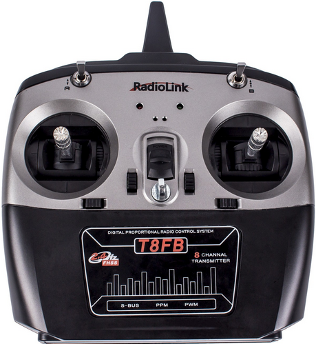
5. CC3D software debugging guide and Radiolink T8FB Remote Controller are provided for you.
Prior to flying the plane, you need to know more about the plane and flight. Please read the following instructions carefully and make sure you understand well before actual flight.
Components Test Before Assembly
Please check whether the components on the list are damaged or missing. Remember to test the components like battery, power indicator alarm, etc., before assembly. If everything works fine, then we can start the test for assembled kit.
1. Battery, Balance Charger and Power Adapter Test
Test Operations:
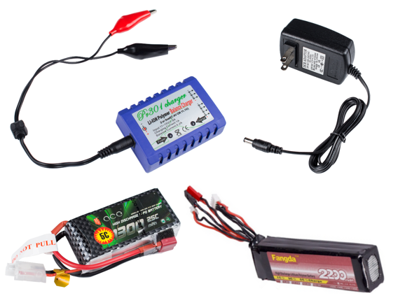
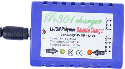
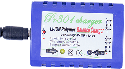
1. Connect the PR301 Li-ion Polymer Balance Charger (Power Charger) and 12V 1.5A Power Adapter, and plug the adapter to a socket. The power indicator on the balance charger will flash green, while the charging indicator orange (as shown in Figure 1-1). The charging indicator will dim one second later (as shown in Figure 1-2), meaning the connection works fine.
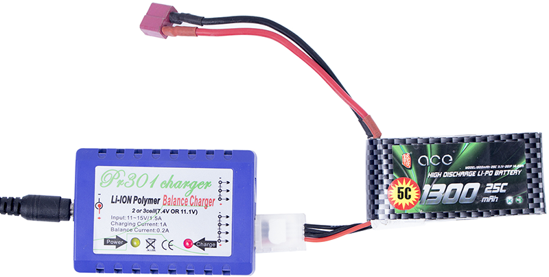
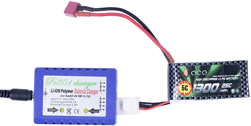
2. Connect the low-power 3S 11.1V 1300m AH T-Plug Li-Po Battery or High Discharge Lithium Polymer Battery(3-cell Li-Polymeter Battery) to the balance charger (DO NOT connect two or three batteries to charger at the same time); Then the charging indicator lights up in red (Figure 1-3), indicating it’s charging.
3. When the charging indicator turns from red to green (Figure 1-4), it means the battery is fully charged.
Note:
1. When you connect the balance charger to power, if the power indicator does not light up, it shows the charger is not well connected to power.
2. If the charging indicator does not light up after you connect the battery to charger, please check the connection, and whether the battery’s voltage is too low (<1.5V/CELL); If a cell is lower than 3V, the charger will provide low current recovery charging for 3 minutes; if it fails, the charging indicator will blink 0.5 seconds, indicating the battery is damaged. Only when each of all the cells reaches 3V, it will turn to normal charging. The charging indicator will light up green when the battery is fully charged. Please take out the battery in time to avoid battery deformation or even explosion caused by overcharging.
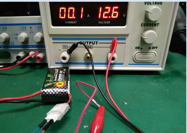
3. The battery may fail to be charged because of over discharging, thus remember to mount a battery indicator alarm. When an alarm beeping is heard, please take out the battery to charge in time! You can try to recover the damaged battery if you have a stabilizator. Here’s how to do:
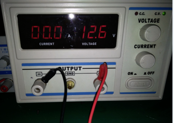
1) Adjust the output voltage to 12.6V as shown in Figure 1-5;
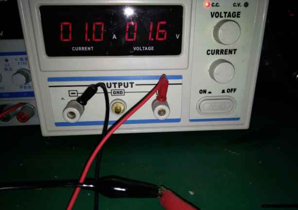
2) Connect the anode and cathode of the stabilizator directely, and adjust the current to 1A (Figure 1-6);
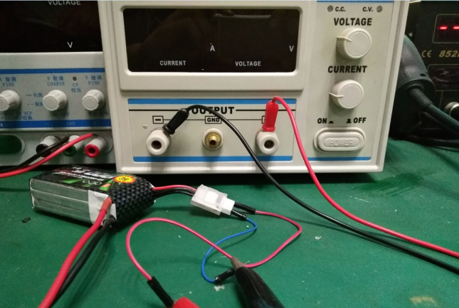
3) TURN OFF the stabilzator, then connect the anode and cathode of the device to those of the battery (Figure 1-7) - use two wires with different length to distinguish from each other so as to avoid short circuit by careless operation;
4) Turn on the device to start the recovery. When the output current changes to 0 or almost 0, the recovery is done as shown in Figure 1-8.
2. Battery Indicator Alarm (with Buzzer) Test
Test Operations:
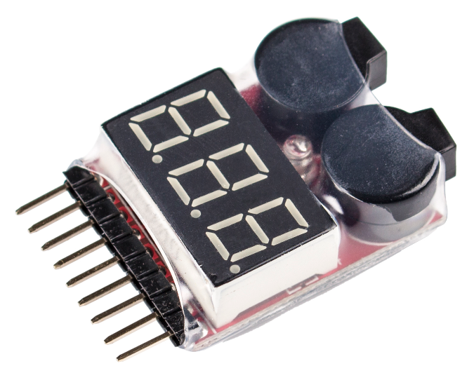
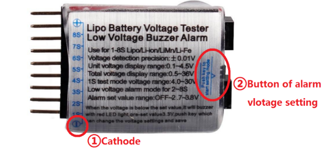
1. Check the back of the Battery Indicator alarm, find the cathode pin marked with “-” (① of Figure 2-1).
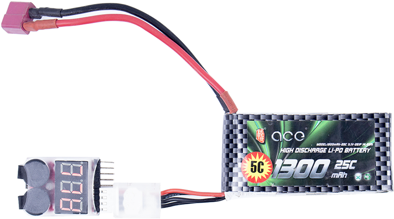
2. Connect the cathode of the Alarm to the first cathode hole of the battery charging cord and the rest pins to the corresponding headers as shown in Figure 2-2.
3. If they are connected correctly, the alarm will beep for three times, and then it will display the total voltage of all the cells and the voltage of each cell, in cycle.
4. The warning voltage threshold can be set by the button on the back of the alarm as shown in ② of Figure 2-1. Each press will add 0.1V and the setting will be saved automatically. The threshold value can be set to OFF (turn off alarm), or from 2.7V (default after manufactured) – 3.8V. You are recommended to set it to 3.7V.
3. Power on Radio Transmitter
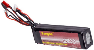
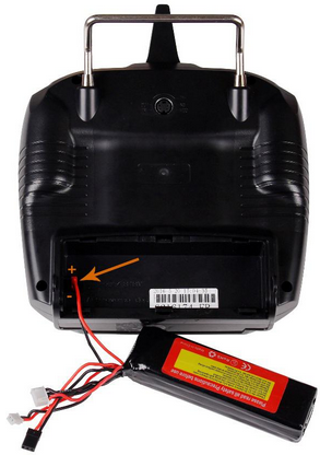
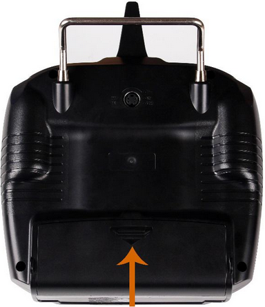
Power on Radio Transmitter: Connect the High Discharge Lithium Polymer Battery to the transmitter as shown in Figure3-1, then insert it in and put the battery cover back (as shown in Figure 3-2).
4. Assembled Kit Test
For this assembled kit, you may still need to mount the propellers, battery and battery indicator alarm before flying it. For security reasons, DO NOT mount the propellers in this step to prevent accidents in later test.
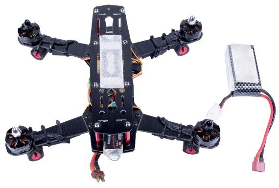
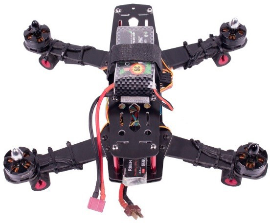
1. Cut the velcro tape into halves, each slightly shorter than the battery, and paste the two pieces on the center of the frame and the back of the battery separately (as shown in Figure 4-1); place the battery on the velcro tape area of the frame, and fix it with a battery strap (as shown in Figure 4-2).
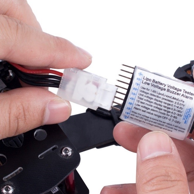
2. Mount the battery indicator alarm to the battery: align the pins and headers to mount the alarm as shown in Figure 4-3, and fix it on the frame with nylon ties.
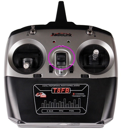
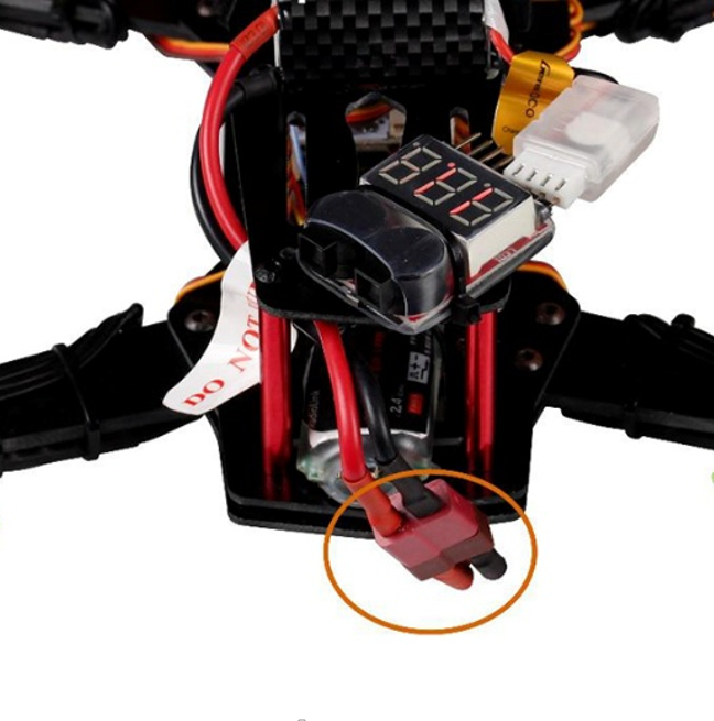
3. Turn on the transmitter (Figure 4-4). Then power on the aircraft: connect the power cord on the plane with that of the battery (Figure 4-5).
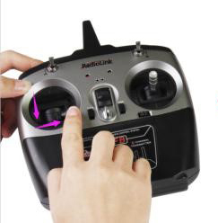
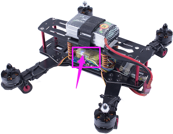
4. Pull the Throttle stick to the bottom and then rightmost (as shown in Figure 4-6), and you can see the blue light on the flight controller blinks. Keep this status for 3 seconds; when the blinking slows down, release the Throttle. Now the aircraft is unlocked successfully.
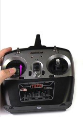
5. Pull the Throttle upward slightly (Figure 4-7), and you can see the motor starts to spin. Note: If you have mounted the propellers unconsciously, DO NOT pull the Throttle stick rapidly, because it’s very DANGEROUS!!!
6. Pull the Throttle to the bottom and then leftmost (Figure 4-8), and keep for 3 seconds; when the blue light’s blinking slows down, release it. Then the aircraft is locked.
5. Trial Flight
If all previous tests work fine, just mount the propellers to start the trial flight.
1. There are two types propellers: CW propeller (Figure 5-1) and CCW propeller (as shown in Figure 5-2). Remember to distinguish the propeller types and mount them as shown in Figure 5-3, with the CW props at No. 1 & 3 and CCW ones at 2 & 4, then fix them with black or white bullet caps separately.
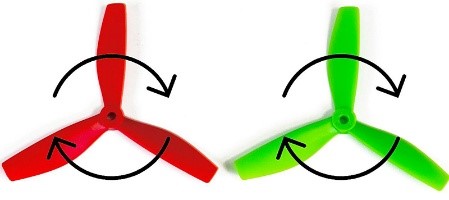
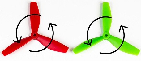
Figure 5-1 & Figure 5-2
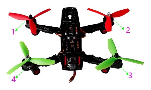
Figure 5-3
2. During the trial flight, you may encounter some problems. For example, the aircraft may tilt to a certain direction in the flight. If so, you need to connect the flight controller to computer for debugging. For more details, please check the instruction manual – CC3D Software Debugging.
Calibration after flight
In the flight previously, you may encounter some problems. For example, the plane keeps tilting toward a certain direction. It may be changed parameter for the plane during the shipment. Take the following steps to calibrate.
1) Calibrate the radio transmitter
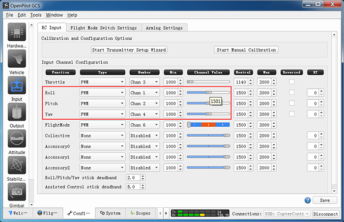
Remove the propellers from the aircraft, connect the flight controller to the computer with a USB cable. Open the Openpilot and click Iuput.
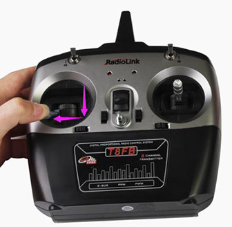
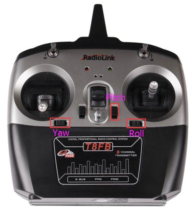
Pull the trimmer toggle for Pitch, Yaw, and Roll, as shown below.
Adjust them until the median is about 1500, click Save.
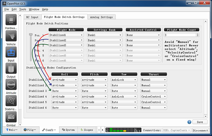
2) Make sure the flight mode channel is pulled to Stabilized1 (self-stabilization)
Click Flight Mode Switch Settings.
Stabilized1: self-stabilization mode - then Roll, Pitch and Yaw are all under the self-stabilization mode.
Stabilized2: semi-self-stabilization mode - Roll and Pitch are self-stabilization when Yaw is still manual.
Stabilized3: manual mode - Roll, Pitch and Yaw are all under the manual mode.
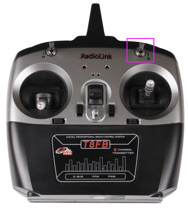
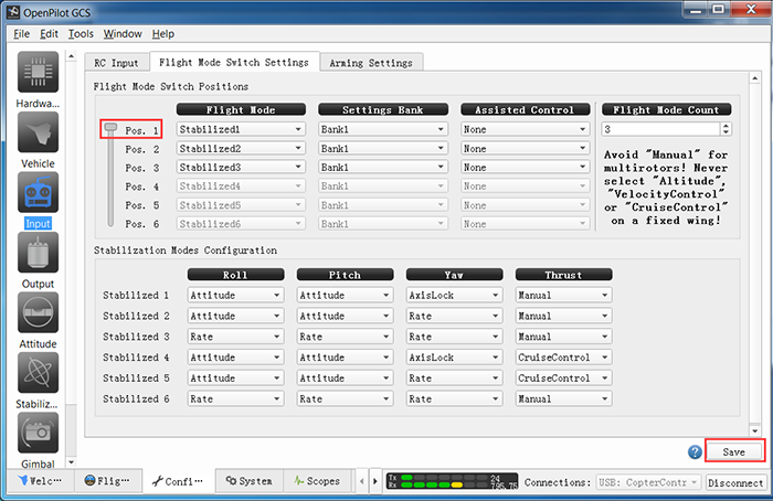
Pull the assistant channel at the right upper corner of the radio transmitter to check the gear corresponding to the flight mode (self-stabilization, semi-self-stabilization, and manual mode).
For example, pull it to the highest, and it is Stabilized1.
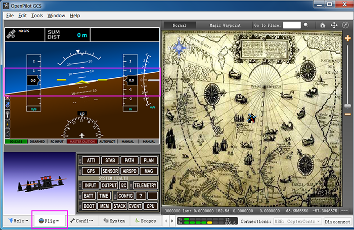
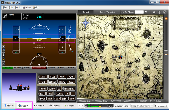
3) Click FlightData to check whether the level line overlaps the yellow line. If yes, it means the calibration is done well; but if not, please move on to the following steps.
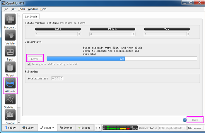
4) Place the plane on a level surface, click Altitude and then Level for the horizontal calibration. After it's done 100%, click Save.
Click Flight Data again and you should see the lines overlapped.
So you've finished the debugging. Now assemble back the propellers to the plane, unlock it, and check whether the drone can fly steadily now.
Note: During the flight, if a crash happens unluckily, the parameters for the plane may change. DO calibrate it again based on the instructions above.
Related links
1.Downlaod the the Ground Control Station (GCS) for the CC3D flight controller board:
Windows:http://wiki.sunfounder.cc/images/3/32/OpenPilot-RELEASE-15.02.02-win32.rar
Mac OS X:http://wiki.sunfounder.cc/images/6/69/Openpilot-release-13.06.04-osx.rar
Note:OPENPILOT WAS DISCONTINUED!
Use LibrePilot instead.
For the latest version of LibrePilot, you can go here to download:
http://opwiki.readthedocs.io/en/latest/user_manual/gcs_install_lp.html
2. For the assembling videos, please refer to this link:
https://www.youtube.com/watch?v=-YJQD8M1F0s
3.The SunFoundere 250 quadcopter kit uses the 5045 propellers blades. you can also choose other 50x propellers blades :
https://www.sunfounder.com/drone/propellers/5030propeller.html
https://www.sunfounder.com/drone/propellers/5045propeller.html
https://www.sunfounder.com/drone/propellers/3-blade.html
4.For the camera kit, you are recommended to refer to this link:
https://www.sunfounder.com/drone/flight-camera/minicamera.html
https://www.sunfounder.com/drone/fpv-image-transceiver-kit-with-700tvl-hd-camera-mini-ts5823-32-channel-av-transmitter-5-8g-mushroom-antenna-for-quadcopter-multirotor-aircraft.html
5. For the FPV TFT LCD, you are recommended to refer to this link:
https://www.sunfounder.com/drone/fpv-lcd.html
6. For the FPV Image Transceiver Kit, you are recommended to refer to this link:
