Difference between revisions of "4X4 Matrix Keypad Module"
(→Experimental Principle) |
|||
| (2 intermediate revisions by the same user not shown) | |||
| Line 1: | Line 1: | ||
=='''Overview'''== | =='''Overview'''== | ||
| − | [[File:Keypad123.jpg]]<br> | + | [[File:Keypad123.jpg]][[File:Keypad-1.jpg]][[File:Keypad-2.jpg]]<br> |
The 4*4 matrix keypad usually is used as input in a project. It has 16 keys in total, which means the same input values.<br> | The 4*4 matrix keypad usually is used as input in a project. It has 16 keys in total, which means the same input values.<br> | ||
The SunFouner 4*4 Matrix Keypad Module is a matrix non- encoded keypad consisting of 16 keys in parallel. The keys of each row and column are connected through the pins outside – pin Y1-Y4 as labeled beside control the rows, when X1-X4, the columns. <br> | The SunFouner 4*4 Matrix Keypad Module is a matrix non- encoded keypad consisting of 16 keys in parallel. The keys of each row and column are connected through the pins outside – pin Y1-Y4 as labeled beside control the rows, when X1-X4, the columns. <br> | ||
| Line 13: | Line 13: | ||
Through programming, we've set the four keys in the first row (with pins at the top as shown in the figure below) as 1, 2, 3, 4; those in the second row as 5, 6, 7, 8; in the third as 9, A, B, C; and in the fourth as D, *, 0, #.<br> | Through programming, we've set the four keys in the first row (with pins at the top as shown in the figure below) as 1, 2, 3, 4; those in the second row as 5, 6, 7, 8; in the third as 9, A, B, C; and in the fourth as D, *, 0, #.<br> | ||
Connect the row and column pins of the keypad to pin 4-11 respectively. You can know its value whenever you press the key.<br> | Connect the row and column pins of the keypad to pin 4-11 respectively. You can know its value whenever you press the key.<br> | ||
| − | [[File:Tupian.jpg]]<br> | + | [[File:Tupian.jpg]][[File:Keypad-4.jpg]]<br> |
Step 1: Build the circuit<br> | Step 1: Build the circuit<br> | ||
The wiring between the keypad and the SunFounder board:<br> | The wiring between the keypad and the SunFounder board:<br> | ||
| − | [[File:Connectionkeypad.jpg]]<br> | + | [[File:Connectionkeypad.jpg]][[File:Keypad-5.jpg]]<br> |
| − | [[File:Keypadfrizting.png]]<br> | + | [[File:Keypadfrizting.png]][[File:Keypad-3.jpg]]<br> |
Step 2: Copy the code to the Arduino IDE directory (if you haven't installed the software yet, download at this link: https://www.arduino.cc/en/Main/Software) | Step 2: Copy the code to the Arduino IDE directory (if you haven't installed the software yet, download at this link: https://www.arduino.cc/en/Main/Software) | ||
<pre> | <pre> | ||
| Line 25: | Line 25: | ||
* note: you need to add the Keypad folder under test experiment\code\Library to the Arduino libraries folder | * note: you need to add the Keypad folder under test experiment\code\Library to the Arduino libraries folder | ||
* function: when you press one button, you can see the keyvalue print on the serial monitor | * function: when you press one button, you can see the keyvalue print on the serial monitor | ||
| − | * Keypad SunFounder Uno | + | * Keypad SunFounder Uno |
| − | * X1 | + | * X1 / 8 8 |
| − | * X2 | + | * X2 / 7 9 |
| − | * X3 10 | + | * X3 / 6 10 |
| − | * X4 11 | + | * X4 / 5 11 |
| − | * Y1 4 | + | * Y1 / 4 4 |
| − | * Y2 5 | + | * Y2 / 3 5 |
| − | * Y3 6 | + | * Y3 / 2 6 |
| − | * Y4 7 | + | * Y4 / 1 7 |
* | * | ||
*********************************************************/ | *********************************************************/ | ||
| Line 93: | Line 93: | ||
You can make a lock with this keypad, which is included in our RFID Kit V2.0 for Arduino. You can also download the Password Lock.zip package below, in which the documentation and code are provided.<br> | You can make a lock with this keypad, which is included in our RFID Kit V2.0 for Arduino. You can also download the Password Lock.zip package below, in which the documentation and code are provided.<br> | ||
| − | [ | + | [http://wiki.sunfounder.cc/images/2/29/Password_Lock.zip Password_Lock][[File:ZIP.jpg]] |
Latest revision as of 10:38, 5 September 2019
Overview
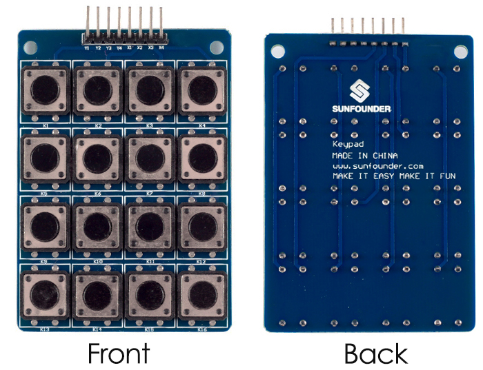
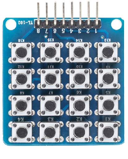
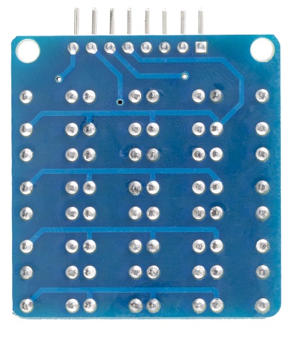
The 4*4 matrix keypad usually is used as input in a project. It has 16 keys in total, which means the same input values.
The SunFouner 4*4 Matrix Keypad Module is a matrix non- encoded keypad consisting of 16 keys in parallel. The keys of each row and column are connected through the pins outside – pin Y1-Y4 as labeled beside control the rows, when X1-X4, the columns.
How it works
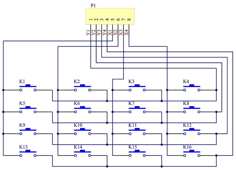
First test whether any key is pressed down. Connect power to rows, so they are High level. Then set all the rows Y1-Y4 as Low and then detect the status of the columns. Any column of Low indicates there is key pressing and that the key is among the 4 keys of the column. If all columns are High, it means no key is pressed down.
Next, locate the key. Since the column in which the pressed key lies is identified, knowing the line would finalize the testing. Thus, set the rows as Low in turns until any is unveiled accordingly – other rows will still be High.
Now the row can be identified. Detect the status of each column in turns. The column tested Low is the one intersecting with the line – their cross point is just the key pressed.
The schmatic diagram:
Test Experiment
Experimental Principle
Through programming, we've set the four keys in the first row (with pins at the top as shown in the figure below) as 1, 2, 3, 4; those in the second row as 5, 6, 7, 8; in the third as 9, A, B, C; and in the fourth as D, *, 0, #.
Connect the row and column pins of the keypad to pin 4-11 respectively. You can know its value whenever you press the key.
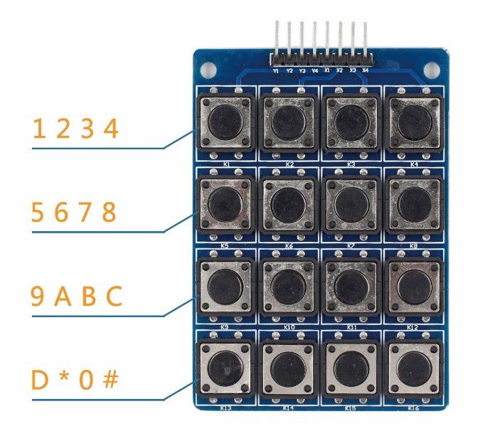
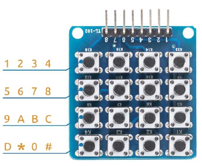
Step 1: Build the circuit
The wiring between the keypad and the SunFounder board:
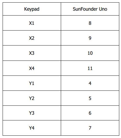
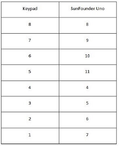
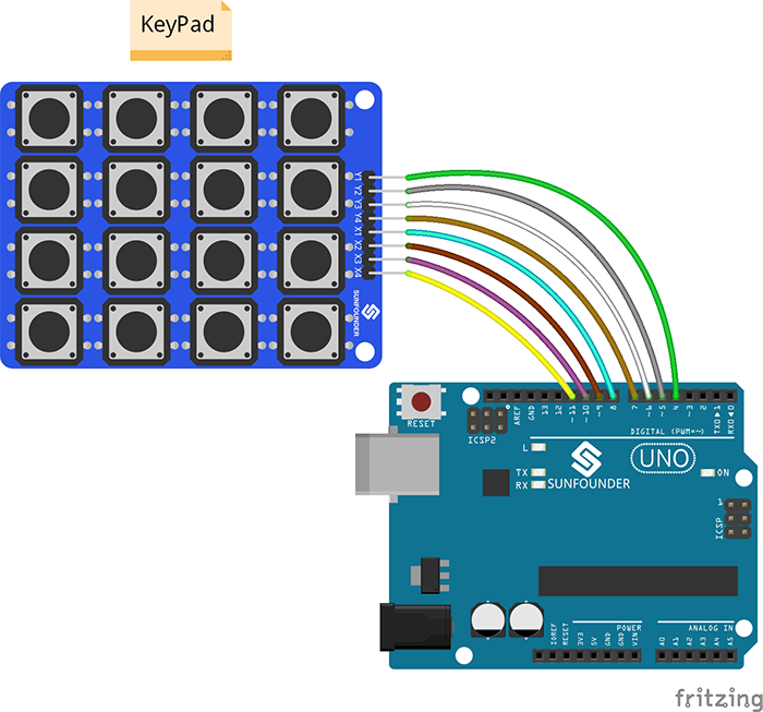
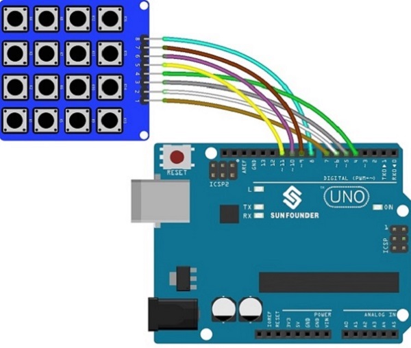
Step 2: Copy the code to the Arduino IDE directory (if you haven't installed the software yet, download at this link: https://www.arduino.cc/en/Main/Software)
//code start
/*******************************************************
 * name: Password Lock
 * note: you need to add the Keypad folder under test experiment\code\Library to the Arduino libraries folder
 * function: when you press one button, you can see the keyvalue print on the serial monitor
 * Keypad	SunFounder Uno
 * X1 / 8	    8
 * X2 / 7	    9
 * X3 / 6           10
 * X4 / 5           11
 * Y1 / 4           4
 * Y2 / 3           5
 * Y3 / 2           6
 * Y4 / 1           7
 *
 *********************************************************/
//Email:support@sunfounder.com
//Website:www.sunfounder.com

#include <Keypad.h>   //use the Keypad libraries

const byte ROWS = 4; //four rows
const byte COLS = 4; //four columns
//define the cymbols on the buttons of the keypads
char hexaKeys[ROWS][COLS] =
{
  {
    '1','2','3','4'      }
  ,
  {
    '5','6','7','8'      }
  ,
  {
    '9','A','B','C'      }
  ,
  {
    'D','*','0','#'      }
};
byte rowPins[ROWS] = { 4, 5, 6, 7}; //connect to the row pinouts of the keypad
byte colPins[COLS] = { 8, 9, 10, 11}; //connect to the column pinouts of the keypad

//initialize an instance of class NewKeypad
Keypad customKeypad = Keypad( makeKeymap(hexaKeys), rowPins, colPins, ROWS, COLS);

void setup()
{
  Serial.begin(9600);
}

void loop()
{
  readKey();
  //delay(100);
}

void readKey()
{
  int correct = 0;
  char customKey = customKeypad.getKey();//get the key value
  if(customKey)
  {
    Serial.print("keyValue: ");
    Serial.println(customKey);
  }
  //delay(100);
}
Step 3: Before you upload the code ,you need to click Tools->Board and Tools->COM to select correct board and COM, then click the Upload icon( )to upload the code the board.
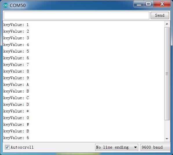
Open Serial Monitor (click ). When you press a key, its value will be displayed on the window.
You can make a lock with this keypad, which is included in our RFID Kit V2.0 for Arduino. You can also download the Password Lock.zip package below, in which the documentation and code are provided.