Difference between revisions of "Joystick PS2 Module"
From Wiki
(→Resource) |
|||
| Line 9: | Line 9: | ||
=='''Resource'''== | =='''Resource'''== | ||
| − | [ | + | [https://www.sunfounder.com/learn/Sensor-Kit-v2-0-for-Arduino/lesson-12-joystick-ps2-sensor-kit-v2-0-for-arduino.html Test Experiment for Arduino][[File:LINK.jpg]]<br> |
| − | [ | + | [https://www.sunfounder.com/learn/sensor-kit-v2-0-for-raspberry-pi-b-plus/lesson-15-joystick-ps2-sensor-kit-v2-0-for-b-plus.html Test Experiment for Raspberry Pi][[File:LINK.jpg]] |
Latest revision as of 02:12, 19 August 2017
Introduction

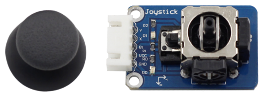
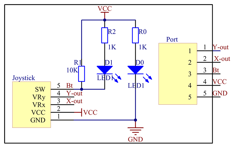
The joystick PS2 module two lines of analog output (X, Y) and one of digital output (Z). The cross rocker is a bidirectional 10k resistor; its resistance changes with different directions. Push the joystick towards different directions and the voltage read increases or decreases; press it down, then the output is low level and the corresponding LED lights up; otherwise it stays off.
The schematic diagram of the module is as follows:

Application
The module can be applied to convenient control of objects (like a two-degree of freedom servo mount) to move in a two-dimensional space. It can be used in the remote controller for many robot projects
Resource
Test Experiment for Arduino![]()
Test Experiment for Raspberry Pi![]()