Difference between revisions of "I²C LCD1602"
(→Download and run the code) |
|||
| (9 intermediate revisions by the same user not shown) | |||
| Line 21: | Line 21: | ||
=='''Backlight/Contrast'''== | =='''Backlight/Contrast'''== | ||
| − | Backlight can be enabled by jumper cap, | + | Backlight can be enabled by jumper cap, unplug the jumper cap to disable the backlight. The blue potentiometer on the back is used to adjust the contrast (the ratio of brightness between the brightest white and the darkest black). |
[[Image:Back lcd1602.jpg|600px]]<br> | [[Image:Back lcd1602.jpg|600px]]<br> | ||
| − | - '''Shorting Cap''': Backlight can be enabled by this | + | - '''Shorting Cap''': Backlight can be enabled by this cap,unplug this cap to disable the backlight.<br> |
- '''Potentiometer''': It is used to adjust the contrast (the clarity of the displayed text), which is increased in the clockwise direction and decreased in the counterclockwise direction.<br> | - '''Potentiometer''': It is used to adjust the contrast (the clarity of the displayed text), which is increased in the clockwise direction and decreased in the counterclockwise direction.<br> | ||
| − | |||
=='''For Arduino User'''== | =='''For Arduino User'''== | ||
| Line 39: | Line 38: | ||
|- | |- | ||
! scope="col" | I2C LCD1602 | ! scope="col" | I2C LCD1602 | ||
| − | ! scope="col" | | + | ! scope="col" | Arduino Board |
|- | |- | ||
| Line 72: | Line 71: | ||
==='''<font color="orange">Copy and Upload the code</font>'''=== | ==='''<font color="orange">Copy and Upload the code</font>'''=== | ||
| − | Copy the | + | Copy the following code to the Arduino IDE, click to the upload icon to upload the code to the control board<br> |
<pre> | <pre> | ||
/******************************** | /******************************** | ||
| Line 108: | Line 107: | ||
| − | You should now see your I2C LCD1602 display the | + | You should now see your I2C LCD1602 display the "SunFounder" and "hello, world".<br> |
[[File:I2c_lcd102_1.png|1000px]] | [[File:I2c_lcd102_1.png|1000px]] | ||
| − | |||
==='''<font color="orange">Read I2C Address</font>'''=== | ==='''<font color="orange">Read I2C Address</font>'''=== | ||
| − | If | + | If the display is functioning properly but only shows 16 black rectangles on the line, it's likely that the I2C address is not set to 0x27. In this case, you should run the following code to determine the correct address and then replace '0x27' with the address you find. |
| + | |||
<pre> | <pre> | ||
LiquidCrystal_I2C lcd(0x27,16,2); | LiquidCrystal_I2C lcd(0x27,16,2); | ||
| Line 120: | Line 119: | ||
<pre> | <pre> | ||
/***************************************************** | /***************************************************** | ||
| − | * | + | * Name: I2C_Address |
| − | * | + | * Function: Read the address of the I2C LCD1602 |
* Connection: | * Connection: | ||
| − | * I2C UNO | + | * I2C Arduino UNO |
* GND GND | * GND GND | ||
| − | * VCC | + | * VCC 5V |
| − | * SDA | + | * SDA A4 (pin 20 in Mega2560) |
| − | * SCL | + | * SCL A5 (pin 21 in Mega2560) |
********************************************************/ | ********************************************************/ | ||
| − | #include <Wire.h> | + | #include <Wire.h> // Include Wire library for I2C communication |
| − | void setup() | + | void setup() { |
| − | { | + | Wire.begin(); // Initialize I2C communication |
| − | Wire.begin(); | + | Serial.begin(9600); // Start serial communication at 9600 baud rate |
| − | Serial.begin(9600); | + | Serial.println("\nI2C Scanner"); // Print a message to the serial monitor |
| − | Serial.println("\nI2C Scanner"); | + | |
} | } | ||
| − | void loop() | + | |
| − | { | + | void loop() { |
| − | byte error, address; | + | byte error, address; // Declare variables for storing error status and I2C address |
| − | int nDevices; | + | int nDevices; // Variable to keep track of number of devices found |
| − | Serial.println("Scanning..."); | + | |
| − | nDevices = 0; | + | Serial.println("Scanning..."); // Print scanning message |
| − | for(address = 1; address < 127; address++ ) | + | nDevices = 0; // Initialize the device count to 0 |
| − | + | ||
| − | + | // Loop through all possible I2C addresses (1 to 126) | |
| − | + | for (address = 1; address < 127; address++) { | |
| − | + | Wire.beginTransmission(address); // Start a transmission to the I2C address | |
| − | Wire. | + | error = Wire.endTransmission(); // End the transmission and get the status |
| − | error | + | |
| − | if (error == 0) | + | // Check if device responded without error (acknowledged) |
| − | + | if (error == 0) { | |
| − | Serial.print("I2C device found at address 0x"); | + | Serial.print("I2C device found at address 0x"); // Notify device found |
| − | if (address<16) | + | if (address < 16) Serial.print("0"); // Print leading zero for addresses less than 16 |
| − | + | Serial.print(address, HEX); // Print the address in hexadecimal | |
| − | Serial.print(address,HEX); | + | Serial.println(" !"); |
| − | Serial.println(" !"); | + | nDevices++; // Increment the device count |
| − | nDevices++; | + | } else if (error == 4) { // If there was an unknown error |
| − | } | + | Serial.print("Unknown error at address 0x"); // Notify about the error |
| − | + | if (address < 16) Serial.print("0"); // Print leading zero for addresses less than 16 | |
| − | + | Serial.println(address, HEX); // Print the address in hexadecimal | |
| − | Serial.print(" | + | |
| − | if (address<16) | + | |
| − | + | ||
| − | Serial.println(address,HEX); | + | |
} | } | ||
} | } | ||
| + | |||
| + | // After scanning, print the results | ||
if (nDevices == 0) | if (nDevices == 0) | ||
| − | Serial.println("No I2C devices found\n"); | + | Serial.println("No I2C devices found\n"); // No devices found |
else | else | ||
| − | Serial.println("done\n"); | + | Serial.println("done\n"); // Scanning done |
| − | delay(5000); // | + | |
| + | delay(5000); // Wait 5 seconds before the next scan | ||
} | } | ||
| + | |||
</pre> | </pre> | ||
| Line 180: | Line 178: | ||
==='''<font color="orange">Build the circuit</font>'''=== | ==='''<font color="orange">Build the circuit</font>'''=== | ||
| − | [[Image:Raspberry i2c lcd2602.png| | + | [[Image:Raspberry i2c lcd2602.png|800px]]<br> |
==='''<font color="orange">Setup I2C</font>'''=== | ==='''<font color="orange">Setup I2C</font>'''=== | ||
| Line 297: | Line 295: | ||
'''Step 6''': Compile.<br> | '''Step 6''': Compile.<br> | ||
<pre> | <pre> | ||
| − | gcc lcd1602.c | + | gcc lcd1602.c -o lcd1602 -lwiringPiDev -lwiringPi |
</pre> | </pre> | ||
| Line 315: | Line 313: | ||
sudo python lcd1602_show.py | sudo python lcd1602_show.py | ||
</pre> | </pre> | ||
| − | |||
=='''Resources'''=== | =='''Resources'''=== | ||
Latest revision as of 02:33, 15 November 2023
Contents
Introduction
As we all know, though LCD and some other displays greatly enrich the man-machine interaction, they share a common weakness. When they are connected to a controller, multiple IOs will be occupied of the controller which has no so many outer ports. Also it restricts other functions of the controller. Therefore, LCD1602 with an I2C bus is developed to solve the problem.
I2C bus is a type of serial bus invented by PHLIPS. It is a high performance serial bus which has bus ruling and high or low speed device synchronization function required by multiple host system. I2C bus has only two bidirectional signal lines, Serial Data Line (SDA) and Serial Clock Line (SCL). The blue potentiometer on the I2C LCD1602 is used to adjust backlight to make it easier to display on the I2C LCD1602.
- GND: Ground
- VCC: Voltage supply, 5V.
- SDA: Serial data line. Connect to VCC through a pullup resistor.
- SCL: Serial clock line. Connect to VCC through a pullup resistor.
I2C Address
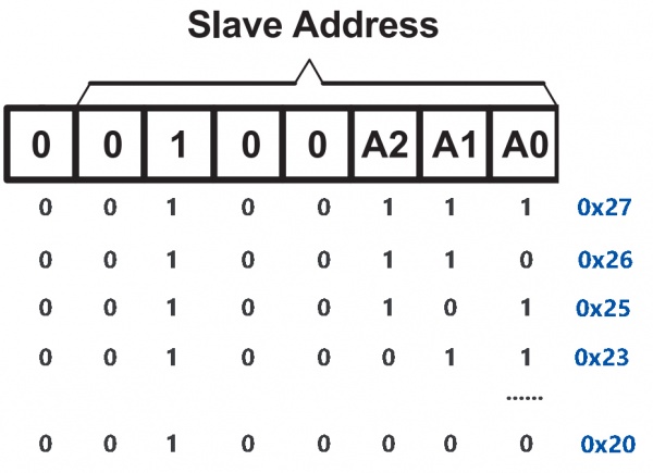
The default address is basically 0x27, in a few cases it may be 0x3F.
Taking the default address of 0x27 as an example, the device address can be modified by shorting the A0/A1/A2 pads; in the default state, A0/A1/A2 is 1, and if the pad is shorted, A0/A1/A2 is 0.
Backlight/Contrast
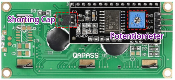
Backlight can be enabled by jumper cap, unplug the jumper cap to disable the backlight. The blue potentiometer on the back is used to adjust the contrast (the ratio of brightness between the brightest white and the darkest black).
- Shorting Cap: Backlight can be enabled by this cap,unplug this cap to disable the backlight.
- Potentiometer: It is used to adjust the contrast (the clarity of the displayed text), which is increased in the clockwise direction and decreased in the counterclockwise direction.
For Arduino User
Build the circuit
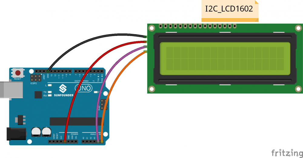
See the following table for connection between the I2C LCD1602 and the SunFounder Uno board:
| I2C LCD1602 | Arduino Board |
|---|---|
| GND | GND |
| VCC | 5V |
| SDA | A4 /pin 20 mega2560 |
| SCL | A5 /pin 21 mega2560 |
Add Library
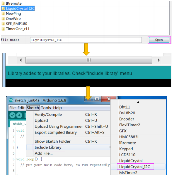
Before you upload the code to the control board,you neeed to add the LiquidCrystal_I2C library.
1) Download the LiquidCrystal_I2C library
2) Open the Arduino IDE,Select Sketch -> Include Library -> Add ZIP Library
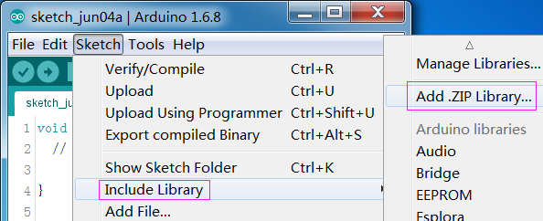
3) Find the file LiquidCrystal_I2C which you just download. Click it open and then you'll be prompted by "Library added to your libraries. Check 'Import libraries'”. You also can see the libraries just imported have appeared on the list by Sketch->Include Library->LiquidCrystal_I2C.
Copy and Upload the code
Copy the following code to the Arduino IDE, click to the upload icon to upload the code to the control board
/********************************
   name:I2C LCD1602
   function:You should now see your I2C LCD1602 display the flowing characters: "SunFounder" and "hello, world".
 ********************************/
//Email:support@sunfounder.com
//Website:www.sunfounder.com

/********************************/
// include the library code
#include <Wire.h>
#include <LiquidCrystal_I2C.h>
/**********************************************************/
LiquidCrystal_I2C lcd(0x27, 16, 2); // set the LCD address to 0x27 for a 16 chars and 2 line display
/*********************************************************/
void setup()
{
  lcd.init();  //initialize the lcd
  lcd.backlight();  //open the backlight
}
/*********************************************************/
void loop()
{
  lcd.setCursor(3, 0); // set the cursor to column 3, line 0
  lcd.print("SunFounder");  // Print a message to the LCD

  lcd.setCursor(2, 1); // set the cursor to column 2, line 1
  lcd.print("Hello, World!");  // Print a message to the LCD.
}
/************************************************************/
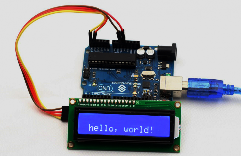
Experimental Phenomenon
You should now see your I2C LCD1602 display the "SunFounder" and "hello, world".
Read I2C Address
If the display is functioning properly but only shows 16 black rectangles on the line, it's likely that the I2C address is not set to 0x27. In this case, you should run the following code to determine the correct address and then replace '0x27' with the address you find.
LiquidCrystal_I2C lcd(0x27,16,2);
/*****************************************************
 * Name: I2C_Address
 * Function: Read the address of the I2C LCD1602
 * Connection:
 * I2C                 Arduino UNO
 * GND                 GND
 * VCC                 5V
 * SDA                 A4 (pin 20 in Mega2560)
 * SCL                 A5 (pin 21 in Mega2560)
 ********************************************************/

#include <Wire.h>  // Include Wire library for I2C communication

void setup() {
  Wire.begin();                     // Initialize I2C communication
  Serial.begin(9600);               // Start serial communication at 9600 baud rate
  Serial.println("\nI2C Scanner");  // Print a message to the serial monitor
}

void loop() {
  byte error, address;  // Declare variables for storing error status and I2C address
  int nDevices;         // Variable to keep track of number of devices found

  Serial.println("Scanning...");  // Print scanning message
  nDevices = 0;                   // Initialize the device count to 0

  // Loop through all possible I2C addresses (1 to 126)
  for (address = 1; address < 127; address++) {
    Wire.beginTransmission(address);  // Start a transmission to the I2C address
    error = Wire.endTransmission();   // End the transmission and get the status

    // Check if device responded without error (acknowledged)
    if (error == 0) {
      Serial.print("I2C device found at address 0x");  // Notify device found
      if (address < 16) Serial.print("0");             // Print leading zero for addresses less than 16
      Serial.print(address, HEX);                      // Print the address in hexadecimal
      Serial.println(" !");
      nDevices++;                                   // Increment the device count
    } else if (error == 4) {                        // If there was an unknown error
      Serial.print("Unknown error at address 0x");  // Notify about the error
      if (address < 16) Serial.print("0");          // Print leading zero for addresses less than 16
      Serial.println(address, HEX);                 // Print the address in hexadecimal
    }
  }

  // After scanning, print the results
  if (nDevices == 0)
    Serial.println("No I2C devices found\n");  // No devices found
  else
    Serial.println("done\n");  // Scanning done

  delay(5000);  // Wait 5 seconds before the next scan
}
For Raspberry Pi User
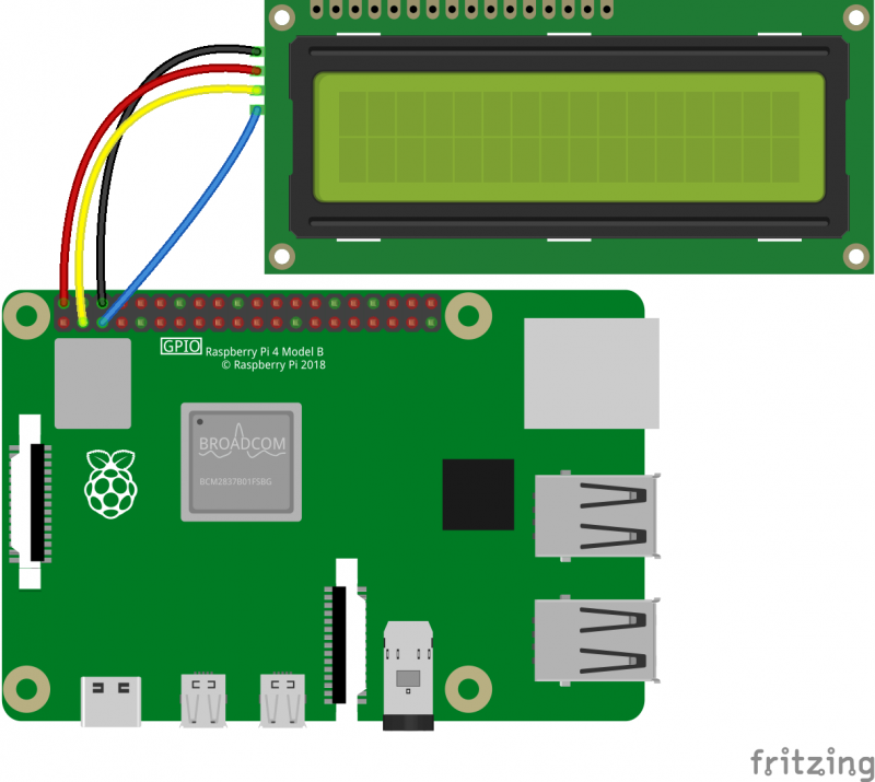
Build the circuit
Setup I2C
Enable the I2C port of your Raspberry Pi (If you have
enabled it, skip this; if you do not know whether you have done that or
not, please continue).
Step 1: Run the following command.
sudo raspi-config
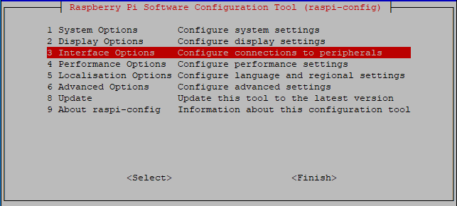
Step 2: 3 Interfacing options.
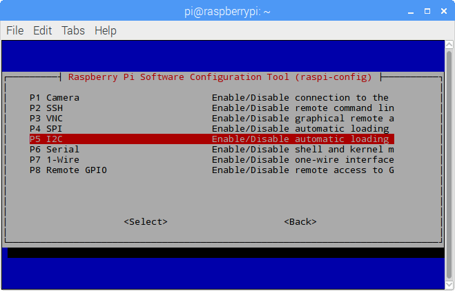
Step 3: P5 I2C.
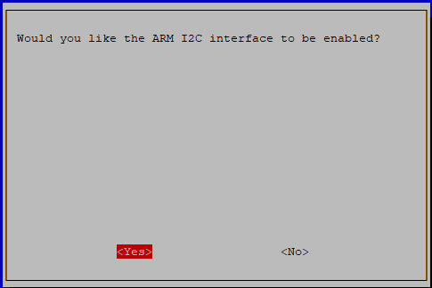
Step 4: <Yes>, then <Ok> -> <Finish>.
Step 5: Check whether the i2c modules are loaded and active.
lsmod | grep i2c
Step 6: Then the following codes will appear (the number may be different).
i2c_dev                     6276    0
i2c_bcm2708                 4121    0
Step 7: Install i2c-tools.
sudo apt-get install i2c-tools
Step 8: Check the address of the I2C device.
i2cdetect -y 1 # For Raspberry Pi 2 and higher version
i2cdetect -y 0 # For Raspberry Pi 1
    pi@raspberrypi ~ $ i2cdetect -y 1
        0  1  2  3   4  5  6  7  8  9   a  b  c  d  e  f
    00:           -- -- -- -- -- -- -- -- -- -- -- -- --
    10: -- -- -- -- -- -- -- -- -- -- -- -- -- -- -- --
    20: -- -- -- -- -- -- -- 27 -- -- -- -- -- -- -- --
    30: -- -- -- -- -- -- -- -- -- -- -- -- -- -- -- --
    40: -- -- -- -- -- -- -- -- -- -- -- -- -- -- -- --
    50: -- -- -- -- -- -- -- -- -- -- -- -- -- -- -- --
    60: -- -- -- -- -- -- -- -- -- -- -- -- -- -- -- --
    70: -- -- -- -- -- -- -- --
If there is an I2C device connected, the address of the device will be displayed.
Step 9: Install libi2c-dev or smbus.
For C language users
sudo apt-get install libi2c-dev
For Python users
sudo pip3 install smbus2
Download and run the code
Step 1: Download the code package.
wget http://wiki.sunfounder.cc/images/2/2e/I2c_lcd1602_for_raspberry_pi.zip
Step 2: Extract the package
unzip I2c_lcd1602_for_raspberry_pi.zip
(For C Language Users)
Step 3: If you have not installed wiringPi, then you will need to install it first.
sudo apt-get update
git clone https://github.com/WiringPi/WiringPi
cd WiringPi
./build
Step 4: You can test whether the wiringPi library is installed successfully or not by the following instruction.
gpio -v
Step 5: Get into the folder of code.
cd ~/I2c_lcd1602_for_raspberry_pi/c
Step 6: Compile.
gcc lcd1602.c -o lcd1602 -lwiringPiDev -lwiringPi
Step 7: Run.
sudo ./lcd1602
(For Python Users)
Step 3: Get into the folder of code.
cd ~/I2c_lcd1602_for_raspberry_pi/python
Step 4: Run.
sudo python lcd1602_show.py

