Difference between revisions of "TB6612 DC Motor Driver Module"
(→II Control 2 motors with Raspberry pi) |
|||
| (30 intermediate revisions by the same user not shown) | |||
| Line 1: | Line 1: | ||
==Introduction== | ==Introduction== | ||
| + | <center> | ||
[[ File:Tb6612-1.jpg]]<br> | [[ File:Tb6612-1.jpg]]<br> | ||
| − | The TB6612 Motor Driver Module uses TB6612FNG as the driver chip which has large current (1.2A continuous current) and two-channel output in a MOSFET-H bridge structure, and can drive two motors. The motor voltage and the working voltage of the module are separated - VCC for the module: 2.7 V to 5.5 V, and VM for the motor: 15V (Max). But the optimum working voltage of the motor is | + | </center> |
| − | It’s easy to control since you can control the forward and reverse rotation of the two servos by setting the values MA and MB as high or low level | + | The TB6612 Motor Driver Module uses TB6612FNG as the driver chip which has large current (1.2A continuous current) and two-channel output in a MOSFET-H bridge structure, and can drive two motors. The motor voltage and the working voltage of the module are separated - VCC for the module: 2.7 V to 5.5 V, and VM for the motor: 15V (Max). But the optimum working voltage of the motor is 2.5V-13.5V, and it cannot work when the voltage is lower than 2.5V. <br> |
| + | It’s easy to control since you can control the forward and reverse rotation of the two servos by setting the values MA and MB as high or low level, and PWMA and PWMB are to control the rotational speed of the motor; thus, only 4 I/O pins would be occupied. The anti-reverse ports for motor connection and signal input can be plugged firmly and conveniently. With low-voltage detection and thermal shutdown inside the chip to protect the circuit, you don’t need to worry about ruining your project or damaging the main control board.<br> | ||
| + | |||
==Features== | ==Features== | ||
| − | >Uses the TB6612FNG motor driver chip with a maximum output current of 1.2A. <br> | + | > Uses the TB6612FNG motor driver chip with a maximum output current of 1.2A. <br> |
| − | >Firm and convenient wiring, with anti-reverse port for both motor connection and signal input. <br> | + | > Firm and convenient wiring, with anti-reverse port for both motor connection and signal input. <br> |
| − | >Simple control: control two motors simultaneously - MA and MB for direction of the motor, and PWMA and PWMB for rotational speed.<br> | + | > Simple control: control two motors simultaneously - MA and MB for direction of the motor, and PWMA and PWMB for rotational speed.<br> |
| − | >Dual power supply. VCC for the module: 2.7-5.5 V, VM for the motor: 15V (Max).<br> | + | > Dual power supply. VCC for the module: 2.7-5.5 V, VM for the motor: 15V (Max).<br> |
| − | >Small and lightweight, with 3mm mounting holes, suitable for smart cars. <br> | + | > Small and lightweight, with 3mm mounting holes, suitable for smart cars. <br> |
| − | >Built-in thermal shutdown circuit and low-voltage detection. <br> | + | > Built-in thermal shutdown circuit and low-voltage detection. <br> |
| − | >Size: 42 x 32 mm | + | > Size: 42 x 32 mm |
| + | |||
==Experimental Test== | ==Experimental Test== | ||
===I Drive 2 motors with Arduino=== | ===I Drive 2 motors with Arduino=== | ||
| − | + | Drive 2 motors to speed up and slow down.<br> | |
'''Components'''<br> | '''Components'''<br> | ||
-1 x TB6612 Motor Driver<br> | -1 x TB6612 Motor Driver<br> | ||
| Line 24: | Line 28: | ||
'''Step 1. Install the library'''<br> | '''Step 1. Install the library'''<br> | ||
Open the Arduino software, and select '''Sketch''' -> '''Include Library''' ->'''Add .ZIP Library'''.<br> | Open the Arduino software, and select '''Sketch''' -> '''Include Library''' ->'''Add .ZIP Library'''.<br> | ||
| − | + | <br> | |
| − | + | ||
[[File:Tb6612-2.png]]<br> | [[File:Tb6612-2.png]]<br> | ||
| + | <br> | ||
| + | Choose the downloaded zip file and open it.[http://wiki.sunfounder.cc/images/e/ee/SunFounder_TB6612.zip '''''SunFounder_TB6612.zip''''']<br> | ||
| + | <br> | ||
| + | [[File:Tb6612-3.png]]<br> | ||
| + | <br> | ||
'''Step 2. Open the Example'''<br> | '''Step 2. Open the Example'''<br> | ||
Open '''File''' -> '''Examples''' –> '''Sunfounder TB6612 Motor Driver''' -> '''motor''', then upload this example<br> | Open '''File''' -> '''Examples''' –> '''Sunfounder TB6612 Motor Driver''' -> '''motor''', then upload this example<br> | ||
| + | <br> | ||
| + | [[File:Tb6612-3-1.png]]<br> | ||
| + | <br> | ||
'''Step 3. Wiring'''<br> | '''Step 3. Wiring'''<br> | ||
Connect the independent power supply to the module as shown below:<br> | Connect the independent power supply to the module as shown below:<br> | ||
| − | + | {| class="wikitable" | |
| − | + | |- | |
| − | + | |Independent Power Supply | |
| − | + | |TB6612 Motor Driver | |
| + | |- | ||
| + | |VCC | ||
| + | |VM | ||
| + | |- | ||
| + | |GND | ||
| + | |GND | ||
| + | |} | ||
Connect the Arduino UNO to the module:<br> | Connect the Arduino UNO to the module:<br> | ||
| − | + | {|class="wikitable" | |
| − | + | |- | |
| − | + | |Arduino UNO | |
| − | + | |TB6612 Motor Driver | |
| − | + | |- | |
| − | + | |5V | |
| − | + | |VCC | |
| − | + | |- | |
| + | |GND | ||
| + | |GND | ||
| + | |- | ||
| + | |5 | ||
| + | |MA | ||
| + | |- | ||
| + | |6 | ||
| + | |PWMA | ||
| + | |- | ||
| + | |9 | ||
| + | |MB | ||
| + | |- | ||
| + | |10 | ||
| + | |PWMB | ||
| + | |} | ||
Connect the motor to the module:<br> | Connect the motor to the module:<br> | ||
| − | + | {|class="wikitable" | |
| − | + | |- | |
| − | + | |Motor | |
| − | + | |TB6612 Motor Driver | |
| − | + | |- | |
| + | |Black wire | ||
| + | |A1 | ||
| + | |- | ||
| + | |Red wire | ||
| + | |A2 | ||
| + | |- | ||
| + | |Black wire | ||
| + | |B1 | ||
| + | |- | ||
| + | |Red wire | ||
| + | |B2 | ||
| + | |} | ||
Here is how the wiring looks like: <br> | Here is how the wiring looks like: <br> | ||
| − | [[File:Tb6612-4.jpg]] | + | <br> |
| + | [[File:Tb6612-4.jpg]]<br> | ||
| + | <br> | ||
After the example is uploaded, the motor will speed up to rotate and slow down in forward direction, then repeat in the reverse direction. <br> | After the example is uploaded, the motor will speed up to rotate and slow down in forward direction, then repeat in the reverse direction. <br> | ||
You can open the Serial Monitor to see the change of the output PWM value - various from small to larger, and then larger to small. <br> | You can open the Serial Monitor to see the change of the output PWM value - various from small to larger, and then larger to small. <br> | ||
There is a positive correlation between the rotational speed of the motor and the PWM value.<br> | There is a positive correlation between the rotational speed of the motor and the PWM value.<br> | ||
| + | <br> | ||
[[File:Tb6612-5.png]]<br> | [[File:Tb6612-5.png]]<br> | ||
===II Control 2 motors with Raspberry pi=== | ===II Control 2 motors with Raspberry pi=== | ||
| − | '''Step 1. Wiring''' | + | '''Step 1. Wiring'''<br> |
Since the motor will use large amount of power, you need to provide this module with an independent power supply so as to ensure the servo will have adequate supply.<br> | Since the motor will use large amount of power, you need to provide this module with an independent power supply so as to ensure the servo will have adequate supply.<br> | ||
Connect the independent power supply to the module as shown below:<br> | Connect the independent power supply to the module as shown below:<br> | ||
| − | + | {| class="wikitable" | |
| − | + | |- | |
| − | + | |Independent Power Supply | |
| + | |TB6612 Motor Driver | ||
| + | |- | ||
| + | |VCC | ||
| + | |VM | ||
| + | |- | ||
| + | |GND | ||
| + | |GND | ||
| + | |} | ||
Connect the Raspberry pi to the module: | Connect the Raspberry pi to the module: | ||
| − | + | {|class="wikitable" | |
| − | + | |- | |
| − | + | |Raspberry Pi | |
| − | + | |TB6612 Motor Driver | |
| − | + | |- | |
| − | + | |3.3V | |
| − | : | + | |VCC |
| − | + | |- | |
| + | |GND | ||
| + | |GND | ||
| + | |- | ||
| + | |GPIO17 | ||
| + | |MA | ||
| + | |- | ||
| + | |GPIO27 | ||
| + | |PWMA | ||
| + | |- | ||
| + | |GPIO18 | ||
| + | |MB | ||
| + | |- | ||
| + | |GPIO22 | ||
| + | |PWMB | ||
| + | |} | ||
| + | Connect the motor to the module:<br> | ||
| + | {|class="wikitable" | ||
| + | |- | ||
| + | |Motor | ||
| + | |TB6612 Motor Driver | ||
| + | |- | ||
| + | |Black wire | ||
| + | |A1 | ||
| + | |- | ||
| + | |Red wire | ||
| + | |A2 | ||
| + | |- | ||
| + | |Black wire | ||
| + | |B1 | ||
| + | |- | ||
| + | |Red wire | ||
| + | |B2 | ||
| + | |} | ||
Pins of Raspberry Pi:<br> | Pins of Raspberry Pi:<br> | ||
| − | [[File: | + | <br> |
| − | + | [[File:Pi3 gpio.png]]<br> | |
| − | + | <br> | |
| − | + | ||
| − | + | ||
| − | + | ||
| − | + | ||
| − | + | ||
Connect the servo to the module: | Connect the servo to the module: | ||
| − | + | {|class="wikitable" | |
| − | + | |- | |
| − | + | |Motor | |
| − | + | |TB6612 Motor Driver | |
| − | + | |- | |
| + | |Black wire | ||
| + | |A1 | ||
| + | |- | ||
| + | |Red wire | ||
| + | |A2 | ||
| + | |- | ||
| + | |black wire | ||
| + | |B1 | ||
| + | |- | ||
| + | |Red wire | ||
| + | |B2 | ||
| + | |} | ||
| − | '''Step 2. Establish your project:''' | + | '''Step 2. Establish your project:''' <br> |
Log into the Raspberry Pi via ssh, and copy the TB6612 repository from Github:<br> | Log into the Raspberry Pi via ssh, and copy the TB6612 repository from Github:<br> | ||
| − | + | git clone https://github.com/sunfounder/SunFounder_TB6612.git | |
After copying, you will have the package of the TB6612 in Python. Import it into the Python program, and you can use it then. <br> | After copying, you will have the package of the TB6612 in Python. Import it into the Python program, and you can use it then. <br> | ||
Here is a simple example: <br> | Here is a simple example: <br> | ||
1. Create a new file: | 1. Create a new file: | ||
| − | + | mkdir test_TB6612/ | |
2. Copy the package to the file: | 2. Copy the package to the file: | ||
| − | + | cd test_TB6612 | |
| − | + | cp –r /home/pi/SunFounder_TB6612 ./ | |
3. Create a code file | 3. Create a code file | ||
| − | + | touch test_motor.py | |
Here the file structure of your program is like this: <br> | Here the file structure of your program is like this: <br> | ||
test_TB6612/<br> | test_TB6612/<br> | ||
| − | + | <br> | |
| − | + | [[File:Tb6612-6.png]]<br> | |
| − | + | <br> | |
| − | + | ||
| − | + | ||
| − | + | ||
| − | + | ||
| − | + | ||
| − | + | ||
| − | + | ||
With this structure, you can import the Python file successfully. <br> | With this structure, you can import the Python file successfully. <br> | ||
Next, let’s see how to control the motors. <br> | Next, let’s see how to control the motors. <br> | ||
| − | '''Step 3. Code to Drive the motors''' | + | '''Step 3. Code to Drive the motors''' <br> |
| − | + | nano test_motor.py | |
Type in the following code: | Type in the following code: | ||
<pre> | <pre> | ||
| Line 203: | Line 292: | ||
destroy() | destroy() | ||
</pre> | </pre> | ||
| + | Press Ctrl+X to exit, you will be prompted to save the changes, enter Y (save) or N (not saved), and then press the Enter key to exit.<br> | ||
Enter the command to run the example: | Enter the command to run the example: | ||
| − | + | python test_motor.py | |
We will still see the motor speeding up to rotate and slowing down in forward direction, then repeating in the reverse direction, same as shown previously. | We will still see the motor speeding up to rotate and slowing down in forward direction, then repeating in the reverse direction, same as shown previously. | ||
| + | |||
| + | ==Attachment== | ||
| + | |||
| + | [http://wiki.sunfounder.cc/images/f/f4/TB6612_Motor_Driver_REV1.0.pdf '''''Datasheet''''']<br> | ||
| + | [http://wiki.sunfounder.cc/images/e/ee/SunFounder_TB6612.zip '''''SunFounder_TB6612.zip'''''] | ||
Latest revision as of 03:51, 19 November 2020
Contents
Introduction
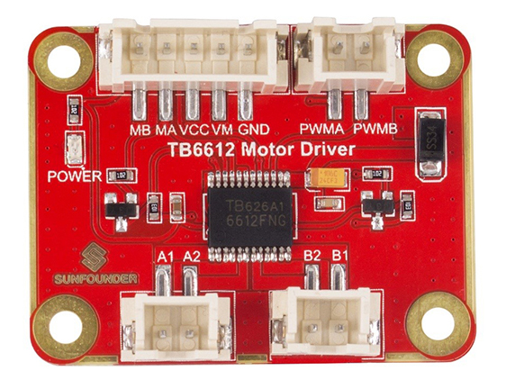
The TB6612 Motor Driver Module uses TB6612FNG as the driver chip which has large current (1.2A continuous current) and two-channel output in a MOSFET-H bridge structure, and can drive two motors. The motor voltage and the working voltage of the module are separated - VCC for the module: 2.7 V to 5.5 V, and VM for the motor: 15V (Max). But the optimum working voltage of the motor is 2.5V-13.5V, and it cannot work when the voltage is lower than 2.5V.
It’s easy to control since you can control the forward and reverse rotation of the two servos by setting the values MA and MB as high or low level, and PWMA and PWMB are to control the rotational speed of the motor; thus, only 4 I/O pins would be occupied. The anti-reverse ports for motor connection and signal input can be plugged firmly and conveniently. With low-voltage detection and thermal shutdown inside the chip to protect the circuit, you don’t need to worry about ruining your project or damaging the main control board.
Features
> Uses the TB6612FNG motor driver chip with a maximum output current of 1.2A.
> Firm and convenient wiring, with anti-reverse port for both motor connection and signal input.
> Simple control: control two motors simultaneously - MA and MB for direction of the motor, and PWMA and PWMB for rotational speed.
> Dual power supply. VCC for the module: 2.7-5.5 V, VM for the motor: 15V (Max).
> Small and lightweight, with 3mm mounting holes, suitable for smart cars.
> Built-in thermal shutdown circuit and low-voltage detection.
> Size: 42 x 32 mm
Experimental Test
I Drive 2 motors with Arduino
Drive 2 motors to speed up and slow down.
Components
-1 x TB6612 Motor Driver
-1 x Arduino Uno
-1 x Motor
-1 x 18650 Battery Holder
-2 x 18650 Li-on Batteries
-Several jump wires
Step 1. Install the library
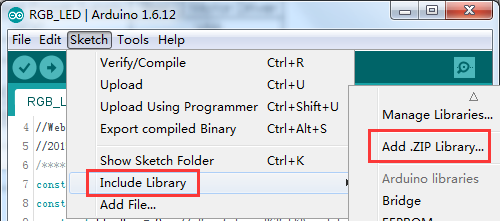
Open the Arduino software, and select Sketch -> Include Library ->Add .ZIP Library.
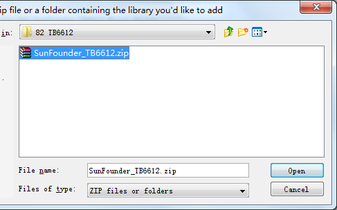
Choose the downloaded zip file and open it.SunFounder_TB6612.zip
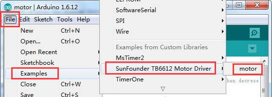
Step 2. Open the Example
Open File -> Examples –> Sunfounder TB6612 Motor Driver -> motor, then upload this example
Step 3. Wiring
Connect the independent power supply to the module as shown below:
| Independent Power Supply | TB6612 Motor Driver |
| VCC | VM |
| GND | GND |
Connect the Arduino UNO to the module:
| Arduino UNO | TB6612 Motor Driver |
| 5V | VCC |
| GND | GND |
| 5 | MA |
| 6 | PWMA |
| 9 | MB |
| 10 | PWMB |
Connect the motor to the module:
| Motor | TB6612 Motor Driver |
| Black wire | A1 |
| Red wire | A2 |
| Black wire | B1 |
| Red wire | B2 |
Here is how the wiring looks like:
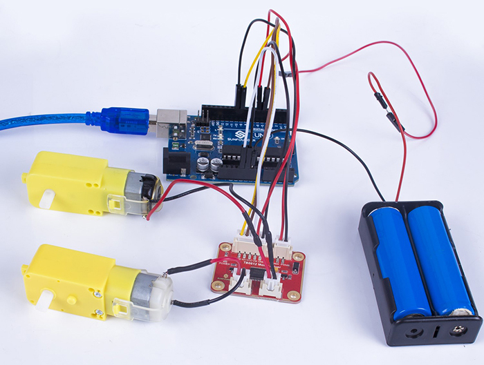
After the example is uploaded, the motor will speed up to rotate and slow down in forward direction, then repeat in the reverse direction.
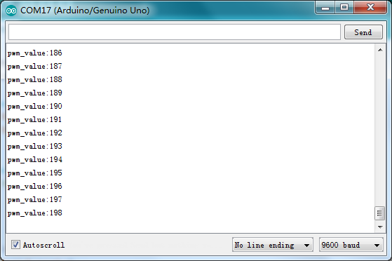
You can open the Serial Monitor to see the change of the output PWM value - various from small to larger, and then larger to small.
There is a positive correlation between the rotational speed of the motor and the PWM value.
II Control 2 motors with Raspberry pi
Step 1. Wiring
Since the motor will use large amount of power, you need to provide this module with an independent power supply so as to ensure the servo will have adequate supply.
Connect the independent power supply to the module as shown below:
| Independent Power Supply | TB6612 Motor Driver |
| VCC | VM |
| GND | GND |
Connect the Raspberry pi to the module:
| Raspberry Pi | TB6612 Motor Driver |
| 3.3V | VCC |
| GND | GND |
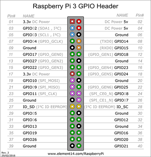
| GPIO17 | MA |
| GPIO27 | PWMA |
| GPIO18 | MB |
| GPIO22 | PWMB |
Connect the motor to the module:
| Motor | TB6612 Motor Driver |
| Black wire | A1 |
| Red wire | A2 |
| Black wire | B1 |
| Red wire | B2 |
Pins of Raspberry Pi:
Connect the servo to the module:
| Motor | TB6612 Motor Driver |
| Black wire | A1 |
| Red wire | A2 |
| black wire | B1 |
| Red wire | B2 |
Step 2. Establish your project:
Log into the Raspberry Pi via ssh, and copy the TB6612 repository from Github:
git clone https://github.com/sunfounder/SunFounder_TB6612.git
After copying, you will have the package of the TB6612 in Python. Import it into the Python program, and you can use it then.
Here is a simple example:
1. Create a new file:
mkdir test_TB6612/
2. Copy the package to the file:
cd test_TB6612
cp –r /home/pi/SunFounder_TB6612 ./
3. Create a code file
touch test_motor.py
Here the file structure of your program is like this:
test_TB6612/
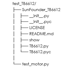
With this structure, you can import the Python file successfully.
Next, let’s see how to control the motors.
Step 3. Code to Drive the motors
nano test_motor.py
Type in the following code:
#!/usr/bin/env python
import time
from SunFounder_TB6612 import TB6612
import RPi.GPIO as GPIO

def main():
	import time

	print "********************************************"
	print "*                                          *"
	print "*           SunFounder TB6612              *"
	print "*                                          *"
	print "*          Connect MA to BCM17             *"
	print "*          Connect MB to BCM18             *"
	print "*         Connect PWMA to BCM27            *"
	print "*         Connect PWMB to BCM22            *"
	print "*                                          *"
	print "********************************************"
	GPIO.setmode(GPIO.BCM)
	GPIO.setup((27, 22), GPIO.OUT)
	a = GPIO.PWM(27, 60)
	b = GPIO.PWM(22, 60)
	a.start(0)
	b.start(0)

	def a_speed(value):
		a.ChangeDutyCycle(value)

	def b_speed(value):
		b.ChangeDutyCycle(value)

	motorA = TB6612.Motor(17)
	motorB = TB6612.Motor(18)
	motorA.debug = True
	motorB.debug = True
	motorA.pwm = a_speed
	motorB.pwm = b_speed

	delay = 0.05

	motorA.forward()
	for i in range(0, 101):
		motorA.speed = i
		time.sleep(delay)
	for i in range(100, -1, -1):
		motorA.speed = i
		time.sleep(delay)

	motorA.backward()
	for i in range(0, 101):
		motorA.speed = i
		time.sleep(delay)
	for i in range(100, -1, -1):
		motorA.speed = i
		time.sleep(delay)

	motorB.forward()
	for i in range(0, 101):
		motorB.speed = i
		time.sleep(delay)
	for i in range(100, -1, -1):
		motorB.speed = i
		time.sleep(delay)

	motorB.backward()
	for i in range(0, 101):
		motorB.speed = i
		time.sleep(delay)
	for i in range(100, -1, -1):
		motorB.speed = i
		time.sleep(delay)

def destroy():
	motorA.stop()
	motorB.stop()

if __name__ == '__main__':
	try:
		main()
	except KeyboardInterrupt:
		destroy()
Press Ctrl+X to exit, you will be prompted to save the changes, enter Y (save) or N (not saved), and then press the Enter key to exit.
Enter the command to run the example:
python test_motor.py
We will still see the motor speeding up to rotate and slowing down in forward direction, then repeating in the reverse direction, same as shown previously.
