Difference between revisions of "Collision Switch Module"
From Wiki
(→Introduction of Pins) |
(→Introduction of Pins) |
||
| Line 15: | Line 15: | ||
</tr> | </tr> | ||
<tr> | <tr> | ||
| − | <td></td> | + | <td>OUT</td> |
| + | <td>VCC</td> | ||
| + | <td>GND</td> | ||
</tr> | </tr> | ||
<tr> | <tr> | ||
| − | <td></td> | + | <td>Switching signal output</td> |
| + | <td>positive pole</td> | ||
| + | <td>negative pole</td> | ||
</tr> | </tr> | ||
</table> | </table> | ||
Revision as of 08:10, 3 September 2019
Introduction
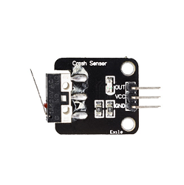
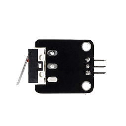
The Crash sensor is a miniature snap-action switch. It is also known as micro switch, an electric switch activated by a small physical force.


feature
- Special module with ports compatible with the expansion board of sensor.
- Output low level when the module is activated; keep outputting high level at the state of release.
- Applied in the detection of collision and touching impact.
Introduction of Pins
| Introduction of Pins | ||
| OUT | VCC | GND |
| Switching signal output | positive pole | negative pole |