Difference between revisions of "Test the PiSmart fuse tutorial"
From Wiki
(Created page with "1. Turn the multimeter to the position shown below. File:piSmarFuseTest1.jpg 2. Use the red and black test leads of the multimeter to test the on/off of the components in...") |
|||
| Line 1: | Line 1: | ||
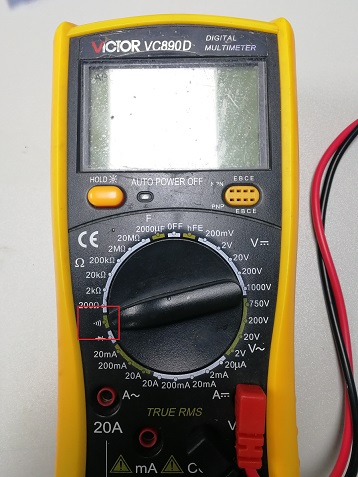
| − | 1. Turn the multimeter to the position shown below. | + | '''1. Turn the multimeter to the position shown below.''' |
| − | [[File:piSmarFuseTest1.jpg]] | + | [[File:piSmarFuseTest1.jpg]]'''Bold text''' |
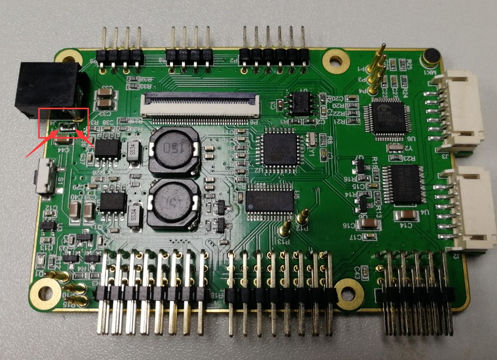
| − | 2. Use the red and black test leads of the multimeter to test the on/off of the components in the figure below. The red and black test leads are respectively in contact with the two ends of the component (the component has "P" written on it). | + | '''2. Use the red and black test leads of the multimeter to test the on/off of the components in the figure below. The red and black test leads are respectively in contact with the two ends of the component (the component has "P" written on it). |
| − | When the multimeter has a sound, it indicates that PiSmart's fuse is good, if not, it indicates that PiSmart's fuse is bad. | + | When the multimeter has a sound, it indicates that PiSmart's fuse is good, if not, it indicates that PiSmart's fuse is bad.''' |
[[File:piSmarFuseTest2.jpg]] | [[File:piSmarFuseTest2.jpg]] | ||
END | END | ||
Revision as of 07:41, 13 November 2018
1. Turn the multimeter to the position shown below.
 Bold text
2. Use the red and black test leads of the multimeter to test the on/off of the components in the figure below. The red and black test leads are respectively in contact with the two ends of the component (the component has "P" written on it).
When the multimeter has a sound, it indicates that PiSmart's fuse is good, if not, it indicates that PiSmart's fuse is bad.
 END
END